|
Why do you need class diagram
modeling?
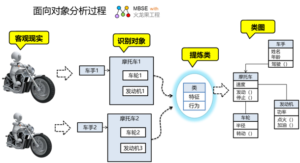
Class diagrams are the crystallization
of object-oriented thinking, which describes things
in the objective world from the perspective of objects:
- An object is an objective
world being that occupies space // such as a wheel
- External performance characteristics
// e.g. radius of wheels
- It interacts with the outside
- An object may be made up of
smaller objects, like molecules with atoms inside
them;
- One object may have a link
to another
- ... ...
There are many objects in the
real world, and in order to describe them concisely
and make it easier to communicate, people abstract
several similar objects into classes:
- Classes exist only in the
human mind, in the human language,£¨
- Give the class a name that
reflects the instance of the object it represents
- Describe the characteristics
of an object with attributes
- Methods describe the behavior
of an object
- A class of a partial object
can make up a class of an entire object
- A class can be associated
with another class
- Several similar classes can
be abstracted as parent classes
- ... ...
The relationships between objects
are abstracted into the relationships of classes:
association, aggregation, composition, generalization,
implementation, and so on.
It's a bit abstract to say, for
example.
When we are faced with complex
logical descriptions, the process of reading is actually
the process of understanding various concepts and
relationships, and object-oriented analysis methods
and class diagrams can greatly improve the efficiency
and accuracy of understanding.
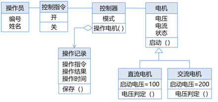
The following is a functional
description of a motor control system, which the engineer
described in text language as follows:
| Description
of the function |
The
operator issues control commands to the controller,
which starts the motor
- If the conditions are met, the motor starts up
with a success message to the operator
- If the conditions are not met, a warning message
is fed back to the operator
There are two types of motors, DC motors and AC
motors, and the starting conditions for voltage
determination are different
- If the DC motor, the voltage reaches 100
volts to start
- If the AC motor, the voltage reaches 200
volts to start
|
If the relevant concepts are
modeled with a class diagram, the model is as follows:
Which is better?
- Easier to understand
- More comprehensive
- It is easier for developers
to translate into system implementations.
I guess readers can judge for
themselves based on their intuition!
What is there in the class diagram
Any UML diagram has semantics,
elements, relationships, and uses, and the following
is a list of class diagrams:
| Semanteme |
Describe the class,
its properties and methods, and the relationships
between the classes |
| Element |
Kind
(class), interface, abstract class |
| Relationship |
Relationships between classes:
- Association-association, aggregation-aggregation,
composition-compose
- Dependency-dependency
- Generalize-generalize
Relationship between classes and interfaces:
|
| Use |
Classify
objects in the objective world, describe features
with attributes, describe behaviors with methods,
and model the relationship between classes to
help users:
- Conceptual modeling
- Data modeling
- Design class modeling
- Implement class modeling
|
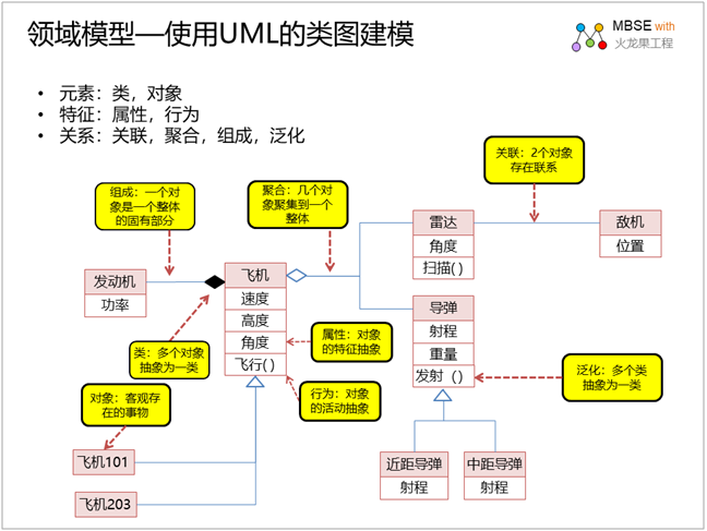
Legend: Domain model
The class diagram can be used
to perform object-oriented analysis of the problem
domain, analyze the properties, methods, and relationships
of various domain objects, and establish a domain
model (also called an analytical model), as shown
in a simplified example of a domain model:
Legend: Design model snake
game class diagram snake
game class diagram
In order to make the reader look
more vivid, the use of legends to introduce the use
of class diagrams, the following is the design class
diagram of the snake game. The difference between
the design class diagram and the analysis class diagram
is that the software implementation environment of
the computer and the development language mechanism
are considered, and a logical view of the solution
is given from the development perspective:
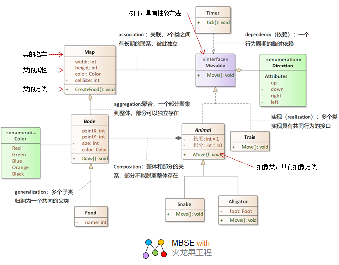
In order to achieve software
robustness, design class diagrams often use design
principles, such as the following:
- Based on the principle of
single responsibility, Map and Food are separated.
- Based on the principle of
interface isolation, the interface Movable is abstracted.
- Based on the principle of
dependency inversion, the interface Movable is placed
on the same layer as the Map.
Class Diagram Description:
The following is a description
dictionary of a class generated from a class diagram:
| Serial
number |
Kind |
Illustrate |
| 1. |
Timer |
The
timer class has a method tick, and when the time
is up, the whole method is triggered - the mobilization
object Move(). |
| 2. |
Map |
Map class, with attributes weight, height, color,
cellSize; Has the method CreateFood(). |
| 3. |
Movable
|
An
interface that can represent a movable object,
with the method declaration Move(). |
| 4. |
Animal |
The
animal class is an abstract class with attributes
Length and integrals, with the abstract method
Move(). |
| 5. |
Node |
Node
class, with properties pointX, pointY, size, color;
Has the method Draw(). |
| 6. |
Food |
The
food class has the attributes name and score. |
| 7. |
Alligator
|
Crocodile,
with the property food and method move(), inherits
the Animal class. |
| 8. |
Snake |
Snakes,
with the method Move(), inherit from the Animal
class. |
| 9. |
Train |
Train
class, with method Move(). |
| 10. |
Direction |
Directional
enumeration type, with values up, down, right,
left. |
| 11. |
Color |
Color
enumeration type with multiple colors: Red, Green,
Blue, Orange, Black. |
The following is a directory of
relationships between classes generated from the class
diagram:
| Serial
number |
Start
class |
Relationship |
Endpoint
class |
| 1. |
Map |
Association |
Movable |
| 2. |
Direction |
Aggregation |
Movable |
|
3. |
Animal |
Realisation |
Movable |
| 4. |
Node |
Aggregation |
Animal |
| 5. |
Food |
Generalization |
Node |
| 6. |
Node |
Aggregation |
Map |
| 7. |
Train |
Realisation |
Movable |
| 8. |
Timer |
Dependency |
Movable |
| 9. |
Alligator |
Generalization |
Animal |
| 10. |
Snake |
Generalization |
Animal |
| 11. |
Node |
Association |
Color |
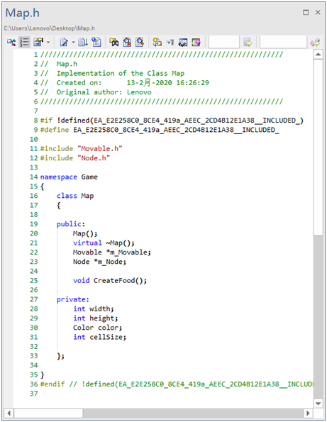
You can generate code based on
class diagrams, as follows the code generated based
on class diagrams (C++ language)
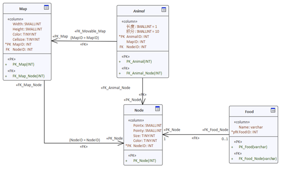
You can generate a data model
based on a class diagram and then generate DDL code
based on the data model. Here's the data model generated
from the class diagram:
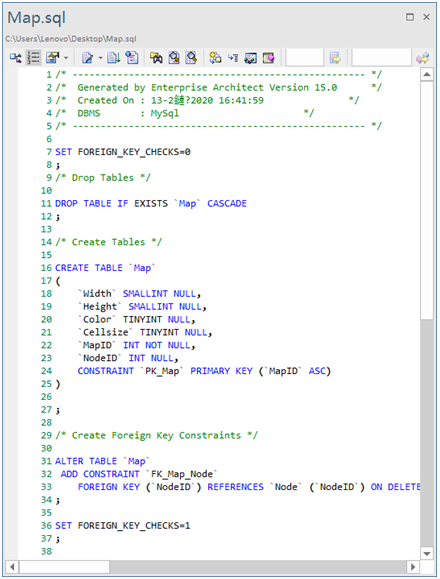
DDL code can be generated based on the data model, as follows:
Note: The model in this paper
uses the modeling tool EA to model, generate code,
and generate database.
UML Diagram Series:
Postscript
I hope you have benefited from reading this.
If you are willing to share your experience, please submit it to us.
If you are interested in our training, consulting and tools:
|