|
1.
Introduction to AUTOSAR
AUTOSAR stands for Automotive Open System Architecture, that is, automotive open system architecture, is a cooperative development framework for automotive electronic systems jointly participated by various automobile manufacturers, parts suppliers and various research and service organizations around the world, and established an open automotive controller (ECU) standard software architecture.
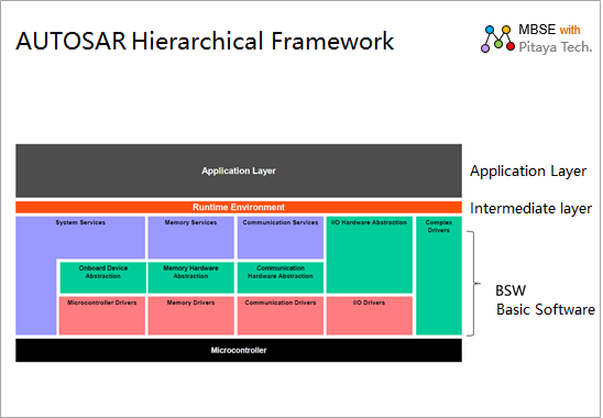
The AUTOSAR hierarchical framework divides software into three layers: the base layer, the middle layer, and the application layer, as shown in the following diagram:
Application layer: provides application components for users' functional requirements.
Middle tier: Services and communication mechanisms that support application components.
Base Layer (BSW): Encapsulates various drivers as the base service.
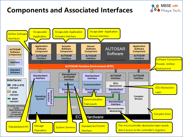
AUTOSAR defines the functions and related interfaces for the basic and middle layers, and provides interface specifications and operating environment support for application layer components, as defined by the AUTOSAR software architecture:
Based on the AUTOSAR architecture, it is easier to divide the work between system design and software development processes, as follows:
Vehicle enterprises define the system architecture, divide the system into subsystems and components, and define the functions and interfaces of subsystems and application components.
The middle layer shields the differences in the underlying drivers, and the interface of the application components mainly focuses on the function, and the mapping with the RTE can be done through configuration.
The underlying technology manufacturer provides BSW in accordance with the BSW specification, and the platform manufacturer provides the implementation of VFS through the RTE specification.
In this way, the upper-layer application vendor can only focus on the system function definition and application component design, and then connect the communication between application components to the BSW through the configuration of RTE, so as to realize the isolation of applications and drivers, and can quickly build applications.
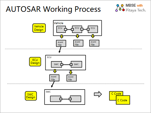
The following is an AUTOSAR-based software development process
Models play a very important role in AUTOSAR-based system design and software development.
Based on modeling, it supports the handover of work between different OEMs and parts manufacturers, and supports code generation from design to development. AUTOSAR also defines pairs Be able to describe the model, components, and interface standards to describe ARXML, so that you need to be able to convert the model into an ARXM L file in your work, as shown in the following figure:
2. EA's support for AUTOSAR modeling
Support required for AUTOSAR implementation:
Modeling
Smulation
Generate ARXML
Generate implementation code for interconnecting BSW and RTE.
At present, the EA can support:
Modeling
Smulation
Generate ARXML
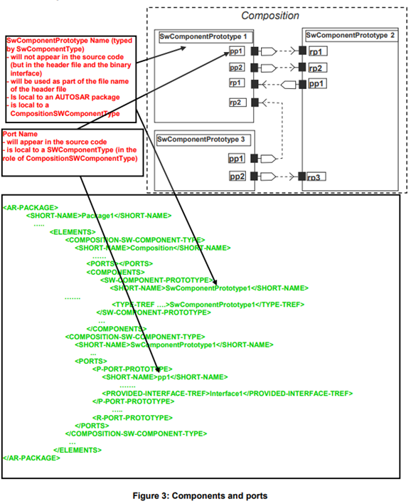
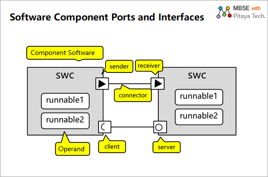
The following are the types of components and interfaces that need to be supported for modeling:
The instructions are as follows:
- Software is divided into software components (SWC) according to application function
- Each software component has an internal Runnable implementation
- There are 2 types of communication ports between software components£ļ
- sender and receiver (sender and receiver, support asynchronous communication)
- client and server (the client acts as the caller and requests the service on the server side, mainly supporting synchronous calls)
These communication ports require implementation support for the respective data types and functions.
As a mainstream modeling tool in the automotive electronics industry, EA provides the systems engineering modeling language Sys The ML and software engineering modeling language UML is supported, and provides modeling extensions for AUTOSAR software architectures, specific model frameworks, and ARXML generation support is provided by: The LiberLiber AUTOSAR Engineering plug-in is complete, and let's take a look at this AUTOSAR plug-in.
3. Overview of AUTOSAR Engineering
AUTOSAR Engineering is EA's AUTOSAR plug-in that supports:
AUTOSAR data type definitions
AUTOSAR data modeling
AUTOSAR component and port modeling
AUTOSAR behavioral modeling
AUTOSAR logical architecture modeling
The generated AUTOSAR component is an ARXML file
Import an ARXML file as an AUTOSAR component
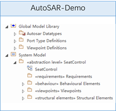
Here's an example of an AUTOSAR Engineering model:
What is this sample model?
The contents of each package are described as follows:
| Pack |
Content |
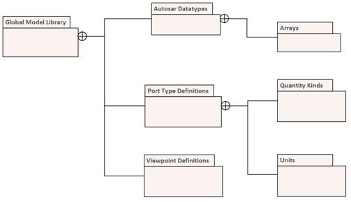
| Global Model Library |
Global model library, including: AUTOSAR Data type, port type definition, and view definition. |
| Autosar DataTypes |
Data type definition for AUTOSAR. |
| Port type Definitions |
Port type definitions for modeling the communication interface between components. include Quantity type and unit of measure. |
| Viewpoint Definitions |
Viewpoint definition, providing a variety of model viewpoints: requirements viewpoint, architecture viewpoint, structural viewpoint, and behavioral viewpoint. |
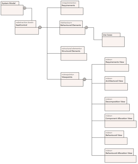
The contents of each package are described as follows:
| Pack |
Content |
| System Model |
A model of the system, using seat control as an example. |
| Requirements |
Customer's demand. |
| Behavioral Elements |
Behavioral elements, such as use case models. |
| Structure Elements |
Various model viewpoints of the system: demand viewpoint, architecture viewpoint, structural decomposition viewpoint, component assignment viewpoint, behavior viewpoint, and behavior assignment viewpoint.
|
4. AUTOSAR Engineering model analysis
4.1 Data Type Modeling
With LieberLieber AUTOSAR Engineer
it is possible to define different data types for
AUTOSAR models, which can be exported to ARXML files,
which support the following data types:
- Generic Base Type
- Data Type
- Value
- Array
- Data Structure
- Port Type Definition
In general, these data type definitions are stored in the EA model's global repository, and in the case of component interfaces, they can also be stored together with AUTOSAR components (i.e. in a folder of structural elements). Inside, as part of the structure of a package at the level of abstraction), the reader can take a quick look at the example model to see how such a model is organized.
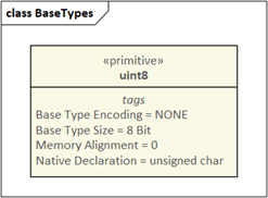
4.1.1 Generic Base Types
Generic Base Type is used to define basic primitive data types, e.g. int, doubule Wait. IN ARXML, IT IS GENERATED INTO A SW-BASE-TYPE XML STRUCTURE.
For example:
4.1.2 Data Types
AUTOSAR data types are usually used to specify values, arrays, and structs, and data type elements have a group of tag values to define additional properties, and in the EA, you can open the tag values window to access the tag values.
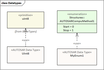
Value
The Value is modeled using the AUTOSAR Data Type element and then set Category Tagged Value is "Value". The image below shows the definition of a numeric value, the value "UInt8" has an AUTOSAR-Usage depends on an AUTOSAR base type, which is based on "uint8" SW-BASE-TYPE°£ Here's the legend:
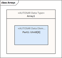
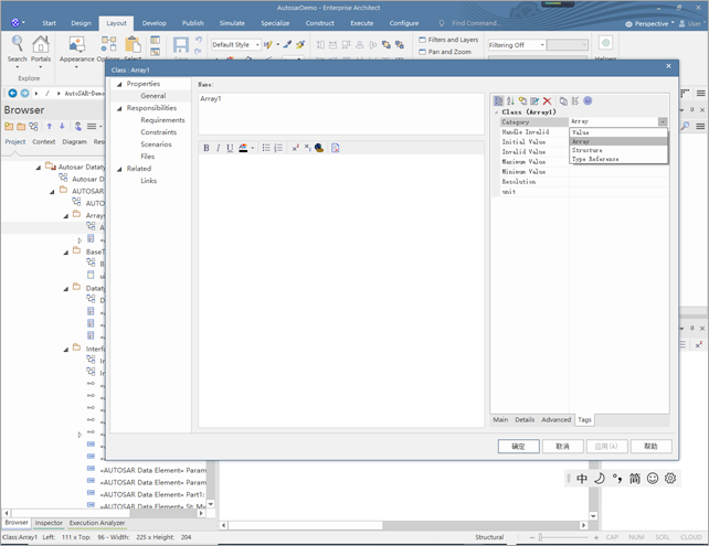
Arrays
Arrays are modeled by putting an AUTOSAR Data Type Category Tagged Value is set to "Array", in order to specify what data types the array element has, one The AUTOSAR Data Type element instance is embedded into the Data Type element, and the size of the Array is specified by the Multiplicity property setting of the embedded Data Element, the following example shows an array of 8 Uint8 type elements, Here's the legend:
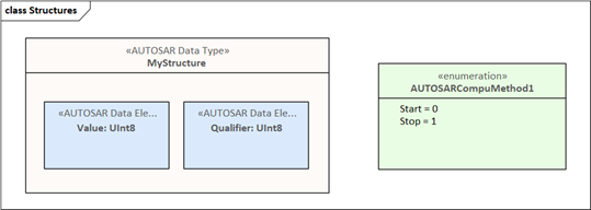
Data Structures
Data Structures does this by adding the AUTOSAR Data Type element to the Category Tagged Value is set to "Structure" to be modeled, and the Structure element is modeled as AUTOSAR Data element (to create an instance of an element of type AUTOSAR Data).
Here's the legend:
Note: A Structure element can contain multiple value elements.
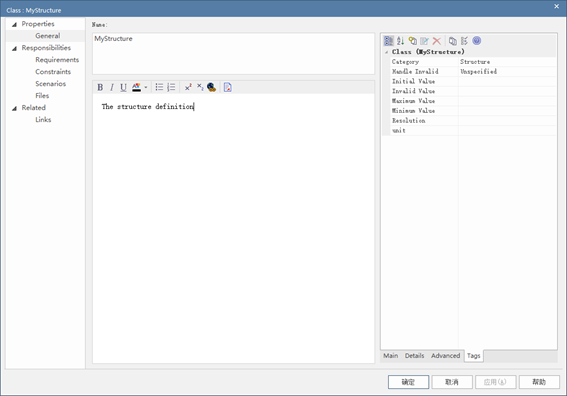
Here is the Category Tagged Value setting property box for the Structure element:
4.1.3 Port Type Definition
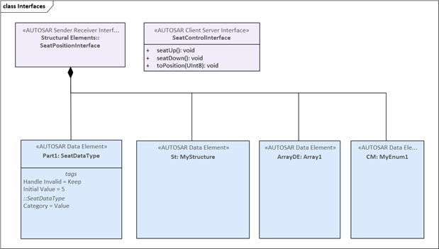
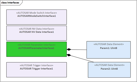
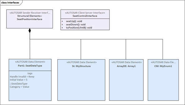
The port type definition is modeled as an interface element (in AUTOSAR Data Modeling toolbox is provided), and for each AUTOSAR port type, there is a corresponding interface element is defined, not all possible port types can be exported as an ARXML file, as shown in the following diagram how to use AUTOSAR The Engineer defines a Sender-Receiver and a Client-Server port type.
For Client-Server-Interfaces, use the EA function to define Operations.
For Sender-Receiver-Interfaces: Define the data element and then create a Part-Association connection (with a black diamond) to specify that the data element is an integral part of the Sender-Receiver-Interface.
Here's an example:
Interface Definition 1:
Interface Definition 2:
4.2 VFB-Models
To create a VFB model with components, the Component is modeled as an instance of the AUTOSAR Component Classifier.
1. Use toolbox or drag an AUTOSAR Component from the Project Browser Classifier onto an AUTOSAR Diagram and select Create/Paste as Instance (AUTOSAR Component).
2. Set the name of the Component on the property box.
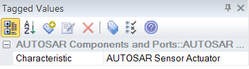
3. Use the Component's Characteristic tagged value to set the Component's characteristics. Here you can choose between 2 different components type (as defined by the AUTOSAR VFB specification).
Once your Component is created, go ahead and add the Interface.
If you don't have a valid Component Classifier, use it The AUTOSAR Type Definition Diagram defines the Data Type.
4.2.1 Adding Interfaces
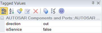
In order to add an interface to a component, it is necessary to use different AUTOSAR Port elements (these elements are found in the LieberLieber AUTOSAR Engineer toolbox). Set the name in the port's options and type (property type). Set the Tagged Value of a port, you can set the direction and a port Is it a service port:
Adding Connections
In order to connect the 2 Ports, the AUTOSAR Flow Connection connector is used. You can also use EA's Quick Linker connects 2 ports or creates a new port and a connection in one step (by creating a connector in an already existing port and a component). LieberLieber AUTOSAR Engineer It will help you by automatically setting the name, port type, and direction of the new port.
Port Direction Determination
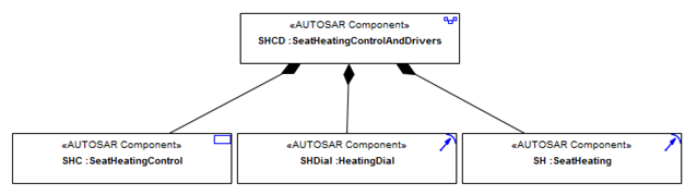
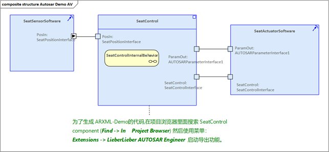
In order to be able to set the port orientation correctly, you have to add a UML Compose or a SysML Part Association connection (with a black diamond) to define the hierarchy of your components. These will define "this component." is the sub-element of another element and the tool is able to set the correct orientation. The following diagram shows an example of a component from this definition (exploded view).
Result
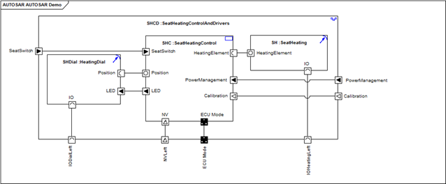
The following diagram shows an AUTOSAR with Component, interface connections (architecture view). Diagram, where the option to "Show Element Stereotype" does not take effect.
4.2.2 Behavior Modeling
The behavior of an AUTOSAR component is modeled on an AUTOSAR behavior diagram. After you have created an AUTOSAR component, you can add an AUTOSAR Behavior elements are used as containers for behavior modeling.
1. Add an AUTOSAR behavior element to your AUTOSAR diagram.
2. Rename the element.
3. Add a Part Association connection from the Behavior Element to the AUTOSAR Component Element to represent that the Behavior Element is part of the assembly.
4. You can add an AUTOSAR behavior subgraph by selecting New Diagram -> Add Diagram from the context menu of the EA Behavior Element.
5. Model the internal behavior using elements such as Runnable and Inter-Runnable-Variables on the AUTOSAR behavior diagram.
Behavior - Multiple instantiations are supported
Each AUTOSAR behavior element has a tag value that sets whether the element can be instantiated multiple times.
Runnable - can be called concurrently
If a Runnable can be called concurrently, you can set this feature using the provided tag value. If a Runnable can be called concurrently, the arrow symbol in the top right corner of the top will be filled with blue, otherwise it won't be filled with blue.
4.3 Types of Diagrams
AUTOSAR Engineer offers three different types of diagrams:
AUTOSAR Type Definition Diagram
AUTOSAR Diagram
AUTOSAR Behavior Diagram
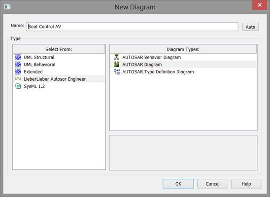
4.3.1 Creating an AUTOSAR Drawing (Autosar Engineer diagram£©
In order to create an AUTOSAR drawing, use EA to add a new drawing. In the dialog box for the new diagram, select LieberLieber Autosar Engineer technology and then select the type of diagram.
4.3.2 AUTOSAR Type Definition Diagram (AUTOSAR Type) Definition Diagram£©
AUTOSAR Type Definiton Diagram (ardd) is used to define data and interface types. This is similar to creating a class before you can create an instance. Use this diagram when you have to define interface and data types.
Here's an example:
When you open an AUTOSAR Type Definition Diagram , the AUTOSAR Data Modeling toolbox opens automatically. This toolbox contains all the necessary elements and connections for defining AUTOSAR data and interface types.
4.3.3 AUTOSAR Diagram
All structured VFB-models are modeled as AUTOSAR Diagrams. When you want to create AUTOSAR with port and internal connections This type of diagram is used when a structured VFB model diagram of a component.
Here's the diagram:
When you open an AUTOSAR Diagram, AUTOSAR The Component and port toolboxes open automatically. This toolbox contains all the necessary elements and connections to define having a port and internally connected AUTOSAR Components.
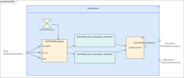
4.3.4 AUTOSAR Behavior Diagram Diagram£©
The AUTOSAR Behavior Diagram (arbeh) is used to model the behavior of an AUTOSAR Component. Typically, this diagram shows Runnable, Inter-Runnable-Variables and Triggers.
Here's an example:
When you open an AUTOSAR Behavior Diagram, AUTOSAR The Behavior toolbox opens automatically, containing all the necessary elements, connections, and internal behaviors for defining AUTOSAR components.
5. How to build an AUTOSAR model in EA
5.1 EA Supported Features for AUTOSAR Modeling
EA supports the following AUTOSAR modeling features:
Support for the AUTOSAR VFB 4 modeling language (component types, interfaces, runables, ...) via a UML2 extension.
User modeling of port type definitions is supported, which can be set on a new connection port: auto-naming, type, and orientation.
Fast linker support.
Hybrid modeling of UML and SysML is possible in a single model library.
ARXML export functionality can be integrated into an AUTOSAR toolchain.
5.1.1 EA LieberLieber AUTOSAR Engineer Toolbox
LieberLieber AUTOSAR Engineer offers three toolboxes:
AUTOSAR Data Modeling Toolbox
AUTOSAR Components and Ports Toolbox
AUTOSAR Behavior Toolbox
These toolboxes contain the elements and connections for creating AUTOSAR models.
5.1.2 AUTOSAR Data Modeling Toolbox
AUTOSAR Data Modeling contains data and interfaces for creating AUTOSAR element.
| |
Name |
Usage |
 |
AUTOSAR Base Type |
Create AUTOSAR base types (e.g. uint8, uint16 etc.). Elements of that kind are generated to a SW-BASE-TYPE element in ARXML. |
| AUTOSAR Client Server Interface |
Defines a Client-Server Interface. Such a Client-Server-Interface is used as the Port-Type for a Client-Server-Port. |
| AUTOSAR Compu Method |
Defines an AUTOSAT Compu Method. |
| AUTOSAR Data Element |
The AUTOSAR Data Element is an instance (Property) of an AUTOSAR Data Type. You can use this element to model internal data attributes of AUTOSAR Data Elements. |
| AUTOSAR Data Type |
AUTOSAR Data Type elements are used to define AUTOSAR data types like Values, Arrays, Structures or Type References. You can set the type with the element tagged values. |
| AUTOSAR Mode Switch Interface |
Defines a Mode-Switch-Interface. This interface type is used for a Mode Switch Port. |
| AUTOSAR NV Data Interface |
Defines a Non-Volatile-Data-Interface. This interface type is used for a NV Data Port. |
| AUTOSAR Parameter Interface |
Defines a Parameter-Interface. This interface type is used for a Parameter Port. |
| AUTOSAR Sender Receiver Interface |
Defines a Sender-Receiver-Interface. This interface type is used for a Sender Receiver Port. |
| AUTOSAR Trigger Interface |
Defines a Trigger-Interface. This interface type is used for a Trigger Port. |
| Part Association |
This connector is used to define a is-part-of relation between interface types and data elements, resp. Data Types. |
| QuantityKind |
Defines a quantity kind, resp. a physical dimension according to the SysML-standard. |
| Unit |
Defines a physical unit according to the SysML-standard. |
| AUTOSAR Usage |
This connector is used to express dependencies between data type element. Have a look into the section about Data Type Modeling for details when to use this conector. |
5.1.3 AUTOSAR Components and Ports Toolbox
The AUTOSAR Components and Ports toolbox contains elements for modeling AUTOSAR components with ports and internal connections. You can set the port orientation and label a port as a service by labeling port°£
| |
Name |
Usage |
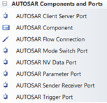 |
AUTOSAR Component |
Defines AUTOSAR Components. The component type is set by a tagged value. |
| AUTOSAR Client Server Port |
Defines a Client-Server-Port for a component. |
| AUTOSAR Sender Receiver Port |
Defines a Sender-Receiver-Port for a component. |
| AUTOSAR Mode Switch Port |
Defines a Mode-Switch-Port for a component. |
| AUTOSAR NV Data Port |
Defines a Non-Volatile-Data-Port for a component. |
| AUTOSAR Parameter Port |
Defines a Parameter-Port for a component. |
| AUTOSAR Trigger Port |
Defines a Trigger-Port for a component. |
| AUTOSAR Flow Connection |
Use this connector to connect two connected ports. |
5.1.4 AUTOSAR Behavior Toolbox
Contains elements that model the internal behavior of AUTOSAR components, such as Runnables and Inter-Runnable-Variable. Not all elements are exported to an ARXML file.
| |
Name |
Usage |
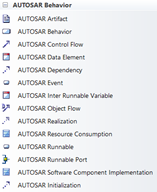 |
AUTOSAR Artifact |
Defines artifacts like .h and .c files in an enar autosar model. |
| AUTOSAR Behavior |
Container used in a AUTOSAR component to contain all behavior elements. This element is based on the structured Activity and you can use the EA-functionality of the Composite Diagram to enable a double-click navigation to the sub-diagram. |
| AUTOSAR Control Flow |
Connects AUTOSAR Events to AUTOSAR Runnables. |
| AUTOSAR Data Element |
Currently unused and reserved for future extensions |
| AUTOSAR Dependency |
Connector used to express dependencies to other model elements. |
| AUTOSAR Event |
Defines AUTOSAR element events (e.g. time events to start a runnable) |
| AUTOSAR Inter Runnable Variable |
Defines Inter-Runnable-Variables. |
| AUTOSAR Object Flow |
This connection is used to connect Runnables and Inter Runnable Variables or Component Ports and AUTOSAR Runnable Ports. |
| AUTOSAR Runnable |
Use this elements to define Runnables as part of the Component Behavior. |
| AUTOSAR Runnable Port |
The Runnable Ports define an interface of a Runnable. They are connected by an AUTOSAR Object Flow connector with a AUTOSAR Component port. |
| AUTOSAR Software Component Implementation |
This element is used to represent a SW Component Implementation. |
| AUTOSAR Initialization |
This connector is used to specify complex data type initializations. |
5.2 How to export an AUTOSAR model to an ARXML file
From an AUTOSAR Engineer model, you can create an AUTOSAR ARXML file that can be used by other AUTOSAR tools. There are three types of ARXML exports:
Select multiple Component components to export as an ARXML file.
Export a Component with no data type to an ARXML file.
Export a Component with all referenced data types to an ARXML file.
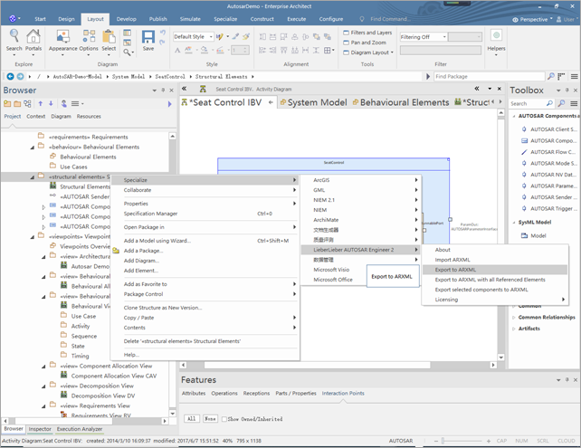
The following is a screenshot of the interface for exporting ARXML from the AUTOSAR Enginee menu in EA:
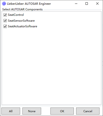
5.2.1 Select multiple Component components to export as an ARXML file
1. Extended Menu ? LieberLieber AUTOSAR Engineer ? Export selected components to ARXML
2. Select the Component you want to export
3. The selected component and all its references will be exported to ARXML File.
5.2.2 Export a Component without a data type to an ARXML file
How to export only one component (no data type) to ARXML:
Select AUTOSAR Component in the Project Browser
1. From the context menu (from the selected element) select: Extensions °ķ LieberLieber AUTOSAR Engineer °ķ Export to ARXML with all Referenced Elements
5.2.3 Export a Component with all referenced data types to an ARXML file
To export a component (with all referenced data types) to an ARXML file, perform the following steps:
1. Select the AUTOSAR component element in the Project Browser.
2. Select the elements you want
to export and select Context Menu: Extensions °ķ LieberLieber
AUTOSAR Engineer °ķ Export to ARXML.
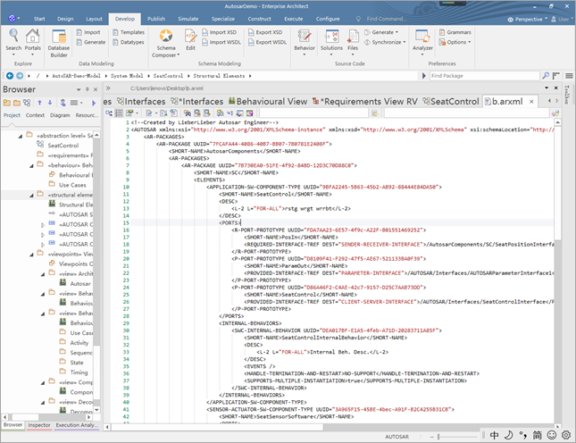
The following is an arxml file generated based on the AUTOSAR model

If you would like to learn more:
Welcome to the Modelers Channelhttp://www.mbse-x.com/
Also welcome to contact us directly a tumlooo@hotmail.com
Postscript
I hope you have benefited from reading this.
If you are willing to share your experience, please submit it to us.
If you are interested in our training, consulting and tools:
|