|
1. Why build a UML model paradigm
As a unified modeling language,
UML can help us sort out a lot of business and technical
knowledge, describe it clearly from multiple perspectives,
and help readers understand. In addition, because
UML modeling comes first and foremost from the needs
of software modeling, UML models are easily translated
into software design, which is a natural benefit for
software developers.
Nowadays, UML has been successful
in modeling IT technologies, such as:
Model data models and
program structures with class diagrams.
Use activity diagrams to model business processes, program flows, computational processes, and so on.
Use sequence diagrams to model human interactions, program module interactions, and more.
Use statecharts to model the state logic of control objects.
But for a complete application,
the most important thing is often the modeling of
highly specialized domain knowledge. In this regard,
there are not many examples of UML that can be seen
publicly, which means that the value of UML modeling
has not been fully explored.
Therefore, we try to use UML
to model the expertise of various fields, hoping to
let everyone see the importance of logical modeling,
and the powerful expression of UML modeling with object-oriented
ideas as the core in logical modeling. As a result,
UML is increasingly used to improve description, analysis,
and design capabilities.
Although UML has a great ability
to express logical modeling, the way each professional
field itself and people spontaneously describe it
is also very important, and it is generally the primary
expression of various professional knowledge. Therefore,
UML modeling should not be a subversive of existing
descriptions, but should be a combing of existing
descriptions, and logical descriptions in a more concise,
more precise and more abstract way. In this way, knowledge
can be more fully excavated and displayed in multiple
dimensions and at multiple levels. Because we are
mainly concerned with UML modeling, but we don't want
to lose the existing knowledge description, we call
the description and modeling methods of various existing
knowledge before UML Native Graph.
So we take a two-way approach
to modeling expertise:
Native diagram: The common
diagram of the field being modeled is used, which
can be a professional diagram or some image diagrams.
UML diagram: UML modeling is adopted, focusing on the description of logic, and more emphasis is placed on the conciseness and clarity of modeling.
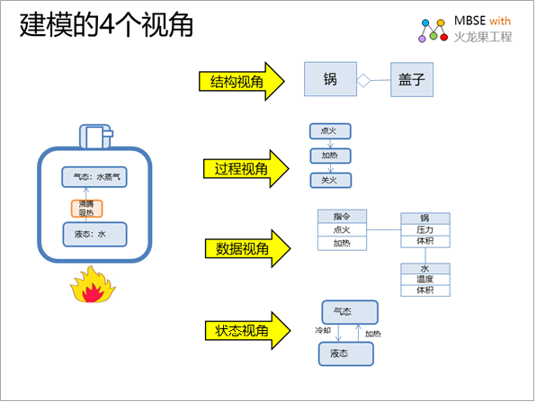
In order to describe the modeled
object more fully, four perspectives are used for
modeling:
Structural perspective:
Describes the composition and relationship of things,
and is a static view.
Process perspective: It
describes the behavioral process of a thing and
is a dynamic view.
Data perspective: Describe
the data passed during the behavior, the data structure
is a static view, and the data transfer is a dynamic
view.
State perspective: describes
the state changes of various objects and behaviors,
the data structure definition of state, belongs
to the static view, the state transition process,
is a dynamic view.
In this paper, the UML model is
used to model the TCP protocol. There are 4 main views
involved:
1. Structure view: Describes
the nodes and links related to the network communication
of the protocol.
2. Process View: Describes the
process of network communication based on this protocol.
3. Data View: Describe the data
structures and relationships related to communication.
4. Status View: Describes the
state of the object during the communication process.
2. Introduction to TCP/IP protocol
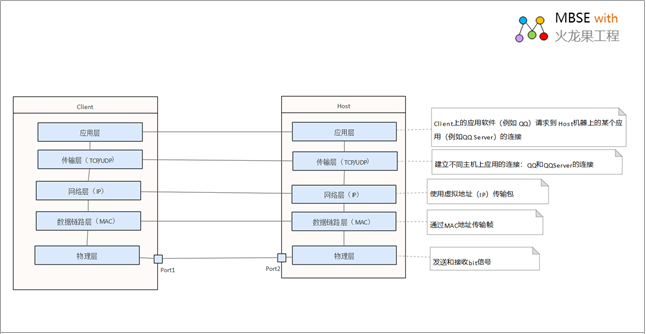
The TCP protocol is the network
communication protocol of the transport layer of the
communication network. In order to fully understand
the TCP 5-layer protocol structure according to TCP/IP,
let's take a look at the responsibilities of each
layer of communication protocols, as shown in the
following figure:
TCP/IP (Transmission Control Protocol/Internet
Protocol) refers to a suite of protocols that can
transmit information between multiple different networks.
The TCP/IP protocol doesn't just refer to TCP and
IP, but refers to a protocol suite composed of FTP,
SMTP, TCP, UDP, IP and other protocols, but because
TCP/IP protocol and IP protocol are the most representative
of TCP/IP protocols, they are called TCP/IP protocols.
Description of the TCP/IP Layer
5 model
| layer |
Duty |
|
Application layer |
The application layer is where the applications
that need to communicate over the network are
located. Examples of these applications include
email clients and web browsers. These applications
use the transport layer to send requests to connect
to remote hosts. |
|
Transport layer |
At the transport layer, connections between applications
running on different hosts are established. It
uses TCP for reliable connections and UDP for
fast connections. It keeps track of the processes
running in the application above it by assigning
it a port number and uses the network layer to
access TCP / IP Network. |
|
Network layer |
This network layer is responsible for creating
packets throughout the network. It uses IP addresses
to identify the source and destination of packets. |
|
Data link layer |
This data link layer is responsible for creating
frames that are transmitted across the network.
These frames encapsulate the packet and use the
MAC address to identify the source and destination. |
|
Physical layer |
The physical layer encodes and decodes a bit in
a frame of the data link layer, which comprises
a transceiver that can generate and receive signals
on the network. |
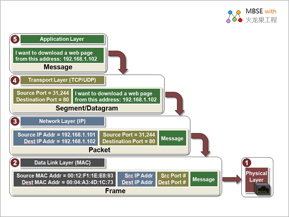
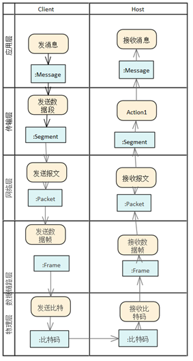
The most important data in the
communication process is the data that is passed through
the various communication protocol layers. The following
is a diagram of a message to be sent as it passes
through the various network protocol layers and the
corresponding protocol information is added step by
step:
The higher layer passes information
to the lower layer. Each layer adds information called
a header to the data passed to it. This header contains
the information that the layer needs to do its job.
We'll start with the application layer.
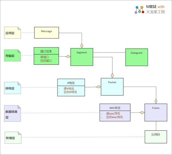
In order to express the changes
in the data structure in the accumulation process,
we use UML class diagram to model the data structure
of each level as follows:
The process of processing messages
at each network communication level is described by
UML activity diagrams, and the data flow is as follows:
| Activity
diagram description |
A
textual description of the process |
|
The application layer generates a message. In
this case, the specific application is the web
browser that requests the download of the web
page. This message is then sent to the transport
layer.
TCP or UDP headers are added to the transport
layer, including the source port and destination
port addresses. Other information, such as
the packet sequence number for TCP, will also
be added to the header. If TCP is used, the
data generated by the transport layer is called
a segment, and if UDP is used, it is called
a datagram. The segment is then sent to the
network layer.
The network layer adds a header containing
the source IP address and the destination
IP address to generate packets. This packet
is then sent to the data link layer.
A header containing MAC address information
is added to the data link layer to create
a frame. This frame is then sent to the physical
layer to transmit the bitcode.
|
3.
UML Modeling Legend
The following uses the 4 views
of UML to model the TCP communication protocol.
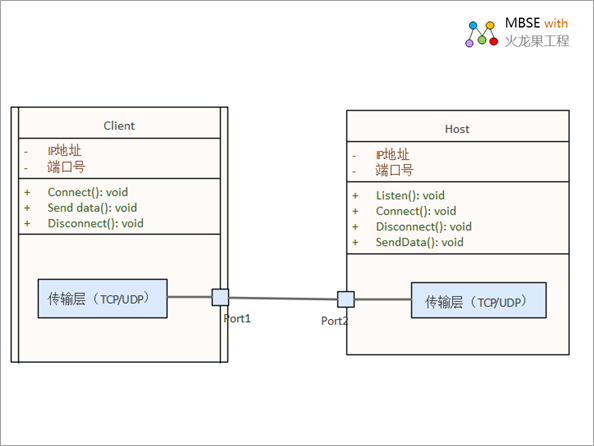
3.1 Structural View
It mainly describes the network
nodes and connections related to the network communication
of the TCP protocol, and the composite structure diagram
of UML is modeled as follows:
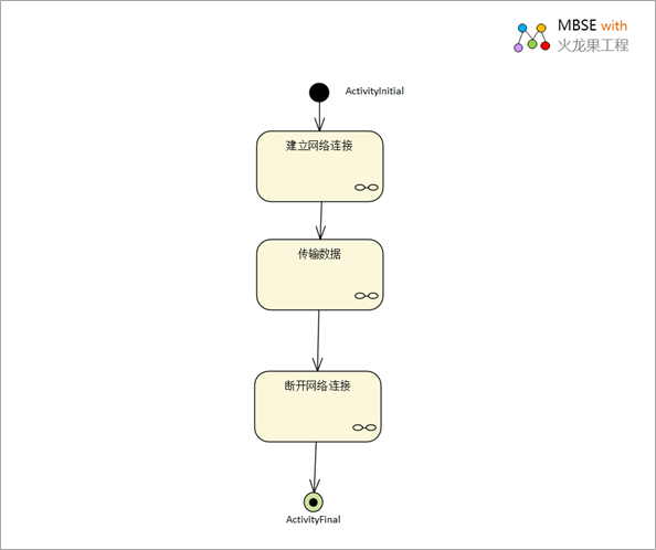
3.2 Process View
The process view mainly describes
the two levels:
The whole process of network
communication
The process of TCP transmission
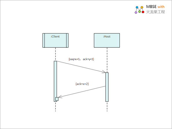
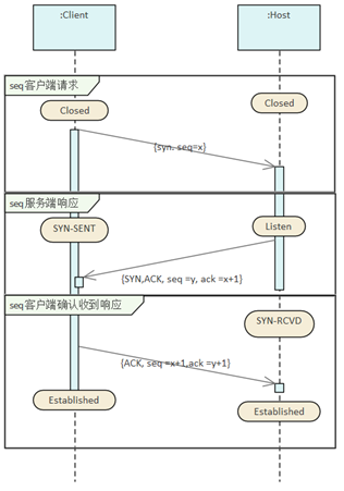
TCP communication process
Establish a connection
Establish a connection between
the client and the server via a three-way handshake
(3 messages):
1. The client makes a request
to establish a connection.
2. Server-side response
3. The client acknowledges receipt
of the response
| A
textual description of the process |
Sequence
diagram description |
Segment 1: The client sends a connection request message
SYN packet description: The TCP/IP packet is
set in the SYN bit field of the TCP header,
and the port number and the initial sequence
number of the client (denoted as ISN, ISN=x
in the figure).
Segment 2: The server responds to the
connection request message
After receiving the request, the server also
sends its own SYN packet segment in response,
including its initial sequence number (ISN(s)=y).
In addition, to check the SYN of the client,
add 1 to the SYN data as the returned ACK value.
Therefore, for each SYN sent, the serial number
is automatically added by 1.
Segment 3: The client sends a message
acknowledging receipt of the response
In order to confirm the SYN on the server side,
the client adds the value of ISN(s) to 1 as
the returned ACK value. This is called paragraph
3.
|
 |
Transfer
of data
The following is a diagram of
the transferred data:
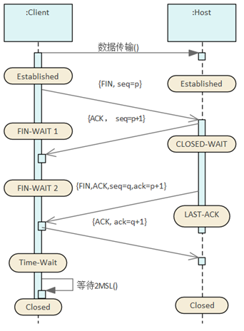
Close the connection
Close the connection between
the client and the server with a four-way handshake
(4 messages):
1. The client makes a close request
2. Confirm on the server
3. The server sends a shutdown
request
4. Client Confirmation
| A
textual description of the process |
Sequence
diagram description |
1. The active closer sends a FIN indicating
their current serial number that the receiver
wants to see. The purpose is to tell the passive
shut-off party that I'm going to close the
connection.
2. After receiving the FIN packet, the passive
closing party sends an ACK to the other party,
adding the value of K to 1 as the ACK value
of the response, to identify the FIN corresponding
to the ACK °£
3. The passive shutdown party sends a FIN
to tell the other party that I can close the
connection as well. To identify that this
is self-initiated, there is a representation
bit seq =q, in order to identify the FIN initiated
by the active closing party corresponding
to the FIN, there will be an identifier ack
= p+1;
4. After receiving the FIN, the active shutdown
party sends an ACK to the other party to inform
them to confirm the closure, and identifies
the corresponding request with an identifier
bit ack = q+1.
|
 |
The
following is a description of the process of closing
a connection from an online article:
|
The first wave: the active
closing party sends a FIN to turn off the data
transmission from the active party to the passive
closing party, that is, the active closing party
tells the passive closing party: I will not
send you any more data (of course, the data
sent before the FIN packet, if the corresponding
ACK acknowledgement packet is not received,
the active closing party will still resend the
data), but at this time, the active closing
party can still accept the data.
Second wave of hand: After
receiving the FIN packet, the passive closing
party sends an ACK to the other party, confirming
that the sequence number is received + 1 (the
same as SYN, one FIN occupies one sequence number).
The third wave: The passive
closing party sends a FIN to turn off the data
transmission from the passive closing party
to the active closing party, that is, telling
the active closing party that my data has also
been sent and will not send you any more data.
Fourth wave: After receiving
the FIN, the active closing party sends an ACK
to the passive closing party to confirm that
the sequence number is received +1, so far,
the fourth wave is completed. |
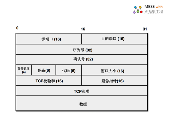
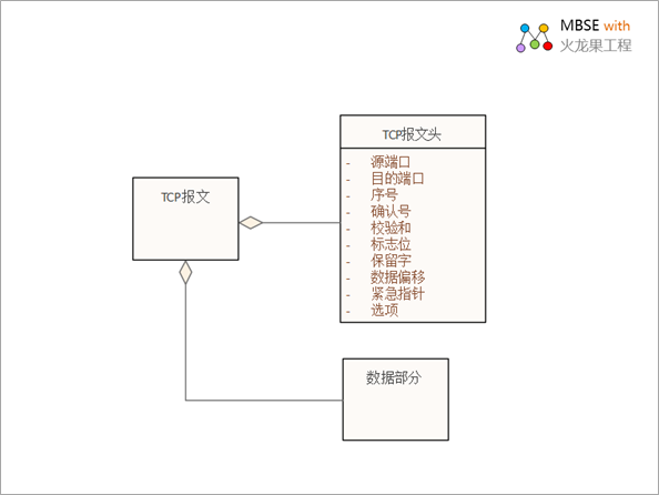
3.3
Data Views
The following figure shows the
structure of a TCP packet:
The packet structure can be modeled
using the UML class diagram, as shown below:
This class diagram describes
the relationship between the structure more clearly,
and also meets the structural needs of the development
engineer. Of course, it is also relatively abstract,
and it should be understood in conjunction with the
native graph.
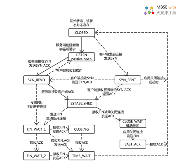
3.4 Status View
Because of the state change of
the communication protocol, the state diagram is generally
used to model the state machine of the protocol. The
following diagram is from a network that is a common
TCP protocol state machine (from a web article):
The following table describes
the TCP status.
| State |
Description |
|
LISTEN |
Wait for a request from the remote TCP application |
|
SYN_SENT |
Wait for an acknowledgment from the remote endpoint
after sending a connection request. The state
of the client after the first TCP handshake |
|
SYN-RECEIVED |
The endpoint has received the connection request
and sent an acknowledgement.
The endpoint is waiting for final confirmation.
The state of the server after the second TCP handshake |
|
ESTABLISHED |
The delegate connection has been established.
This is the normal state of the connection data
transfer phase |
|
FIN_WAIT_1 |
Wait for a termination request from the remote
TCP or an acknowledgment of the termination request |
|
FIN_WAIT_2 |
After this endpoint sends a connection termination
request, wait for the connection termination request
from the remote TCP |
|
CLOSE_WAIT |
The endpoint has received a shutdown request from
the remote endpoint, and this TCP is waiting for
a connection termination request from the local
application |
|
CLOSING |
Wait for the connection termination request from
the remote TCP to be acknowledged |
|
LAST_ACK |
Wait for the acknowledgment of the connection
termination request that was previously sent to
the remote TCP |
|
TIME_WAIT |
Wait long enough to ensure that the remote TCP
receives an acknowledgment of its connection termination
request |
This statechart involves multiple
objects connected to the client, the server, and the
network, so it seems confusing and difficult to understand.
Such diagrams are not user-friendly, so it is necessary
to improve them with UML state diagrams.
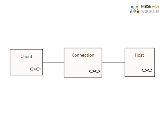
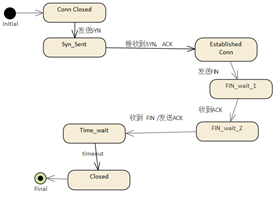
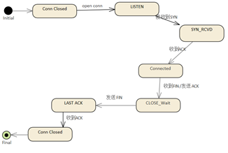
The modeling of the state diagram
should first identify the object that holds the state,
and then build its state diagram, and the TCP network
communication process actually involves 3 objects:
Client
Host
Connection
They each have their own state
diagrams, and the following TCP communication process
is used to model the state of each of the three objects.
| ClientΩ⁄µ„µƒ◊¥Ã¨ |
Hostµƒ◊¥Ã¨ |
|
|
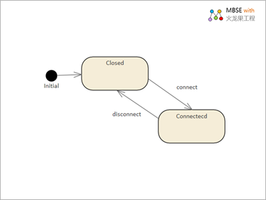
The status of the connection is
as follows
This looks like a complete map
to the communication process, which is much easier
to understand.

I hope
you have benefited from reading this. If you are interested
in UML, welcome to read more articles:
If you
would like to learn more:
Welcome to the Modelers Channel
http://modeler.org.cn/
Also welcome to contact us
directly at zhgx@uml.net.cn £¨010-62670969
About
the Author:
|
Zu Tao,the founder of Pitaya
Software Engineering, founded Pitaya Software
Engineering in 2001 and IBM Rational User Group
in 2004. In 1998, he participated in the national
key research project "Component-based Software
Reuse for Specific Domains" as a backbone,
and was fortunate to learn and use UML for domain
modeling and refining reusable components and
architectures. In the subsequent R&D projects,
the model has been used for analysis and design,
and has accumulated some experience and experience.
Focused on MBSE for 20 years, familiar UML, Sys
ML, ArchiMate, BPMN, UPDM, DataModel and other
modeling languages and specifications, in the
past experience, the biggest feeling is that the
field of software engineering and systems engineering,
which brings together many elite talents, has
been a messy and confused state for decades. Develop
a sustainable methodology for yourself, such as
MBSE From Methodology to Practice Guide Model-Based
3D R&D Management Model-Based Requirements
Management Model-Driven Architecture Design "Model-Based
Quality Management" "Model-based Personnel
Capability Management" "iProcess Process
Improvement Method", currently as a product
manager and architect, is currently working on
the research and development of MBSE (Model-Based
Systems Engineering) platform, hoping to establish
model-based engineering solutions, and will continue
to write some articles in the future, hoping to
give some reference to peers. |
Postscript
I hope you have benefited from reading this.
If you are willing to share your experience, please submit it to us.
If you are interested in our training, consulting and tools:
|