|
Note: Most of the legends in this
article are from the UML 2.4.1 and UML 2.5.1 specification
documents, and some of the legends have been reconstructed
using the modeling tools EA and iSpace in order to
improve readability.
Preface
Recently, he helped a client establish
a modeling language specification for a certain domain,
using metamodel modeling. In order to refer to the
metamodel and MOF (Meta Object Facility) of UML, I
looked at the specification document of UML 2.5.1
and found that the structure of the specification
is completely different from that of UML 2.4. I feel
the need to write an article about the differences
between the two, which can be used as a reference
for modelers.
The composition of the UML 2.4.1
specification
Recall that before UML 2.5, the
UML specification would publish two documents:
• UML Infrastructure:
UML Infrastructure: Mainly provides a metamodel modeling
mechanism for UML.
• UML Superstructre:
UML Superstructure: Provides semantic descriptions,
appearances, and meta-model mechanisms for the various
elements and diagrams of UML.
The following are the documents
related to the two specifications of UML 2.4.1.
Here's an overview of the UML
2.4.1 specification:
The following is an excerpt from
the UML 2.4.1 specification
UML Infrastructure
UML Infrastructure is defined
by the infrastructure Library, and its goals are:
• Define a metalanguage core that
can be reused to define a variety of metamodels, including
UML, MOF, and CWM.
• Architecturally align
UML, MOF, and XMI for full support for model exchange.
• Allows customization
of UML via profiles and the creation of new languages
(language families) based on the same metalinguistic
core as UML.
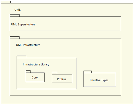
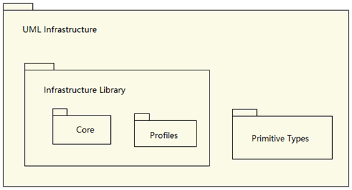
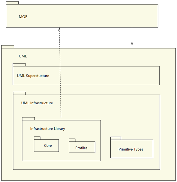
The contents of UML Infrastructure
are shown in the following diagram:
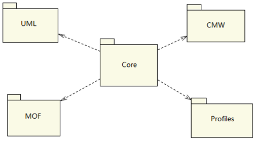
The Core package defines the metaclass
and abstract syntax for building metamodels for other
models. Profile provides a mechanism to extend other
modeling languages from metaclasses. The Core package
can be used as a basis for other modeling languages
(UML, CWM), as well as as a basis for MOF.
After extracting MetaClasses from
the Core package, building a MOF specifically for
defining the metamodel, and using the MOF as the basis
for defining UML. This is the foundation of MDA.
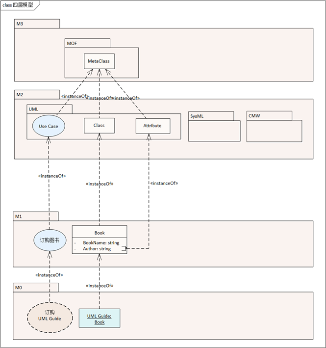
Modeling is a process from abstraction
to concreteness, which can be divided into four levels
according to the degree of abstraction of the model:
• M3: Meta-model for
building models of other models.
• M2: Metamodel, which
is used to model a specific domain, and UML is at
this level
• M1: Domain-specific
models, e.g. software models, business process models
• M0 £∫Runtime instance
model.
Here's a diagram of the model
hierarchy from UML Infrastructure:
UML Superstructure
UMLSuperstructure is the definition
of the UML specification itself.
The modeling concepts of UML are
grouped into language units. A language unit consists
of a set of tightly coupled modeling concepts that
provide users with the ability to represent aspects
of the system under study according to a specific
paradigm or form. For example, the State Machines
language unit allows modelers to specify discrete
event-driven behaviors using variations of the well-known
state diagram form, while the Activities language
unit provides behavioral modeling based on workflow
examples. From a user's point of view, this division
of UML means that they only need to care about the
parts of the language that they think are necessary
for their model. If these needs change over time,
you can add more linguistic units to the user's model
library as needed. Therefore, UML users do not need
to know the full language to use it effectively.
UML's set of modeling concepts
is divided into horizontal layers of increasing capabilities,
known as compliance levels. The level of compliance
spans a variety of linguistic units, although some
linguistic units only exist at higher levels. As the
name suggests, each level of compliance is a unique
point of compliance.
To simplify model exchange, only
four levels of compliance are defined for the entire
UML:
• Level 0 (L0). This
level of compliance is formally defined in the UML
infrastructure. It contains a single linguistic unit
for modeling class-based constructs encountered in
most popular object-oriented programming languages.
As a result, it provides entry-level modeling capabilities.
More importantly, it represents a low-cost common
foundation that can serve as a basis for interoperability
between different classes of modeling tools.
• Level 1 (L1). This
level adds new language units and expands on the features
offered by level 0. Specifically, it adds linguistic
units for use cases, interactions, structures, actions,
and activities.
• Level 2 (L2). This
level expands on the language units already provided
in Level 1 and adds language units for Deployment,
State Machine Modeling, and Profiles.
• Level 3 (L3). This
layer represents the full UML. It expands the language
units provided by Level 2 and adds new language units
for modeling information flows, templates, and model
packaging.
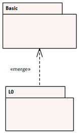
L0 is explained
Level 0 is defined by the top-level
metamodel, as shown in Figure 2.1. In this model,
"L0" starts out as an empty package, which
simply merges the contents of the base package from
the UML infrastructure. This package is then merged
into the UML model. Package L0 contains basic concepts
such as classes, packages, data types, operations,
etc., which are merged from Basic, which comes from
nfrastructure.
Figure 2.1-Level
0 package diagram
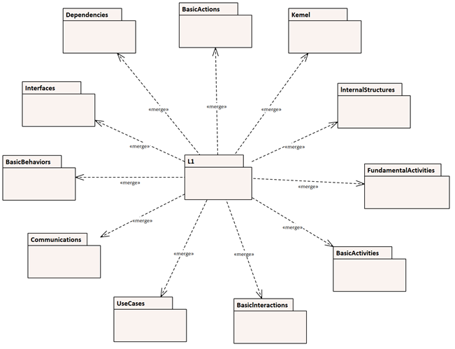
Interpretation of L1
L1 is built on the L0 level. The
set of language units derived from this model is much
larger than that represented by the L0 model, as shown
in Figure 2.2.
Figure 2.2 ®CLevel
1 top-level package merges
Table 2.3 lists the
specific packages for this level.
Table 2.3 - Metamodel
packages added in Level 1
| Language Unit
|
Metamodel Packages
|
| Actions |
Actions::BasicActions |
| Activities |
Activities::FundamentalActivities |
| Activities::BasicActivities |
| Classes |
Classes::Kernel |
| Classes::Dependencies |
| Classes::Interfaces |
| General
Behavior |
CommonBehaviors::BasicBehaviors |
| CommonBehaviors::Communications |
| Structures |
CompositeStructure::InternalStructures |
| Interactions |
Interactions:BasicInteractions |
| UseCases |
UseCases |
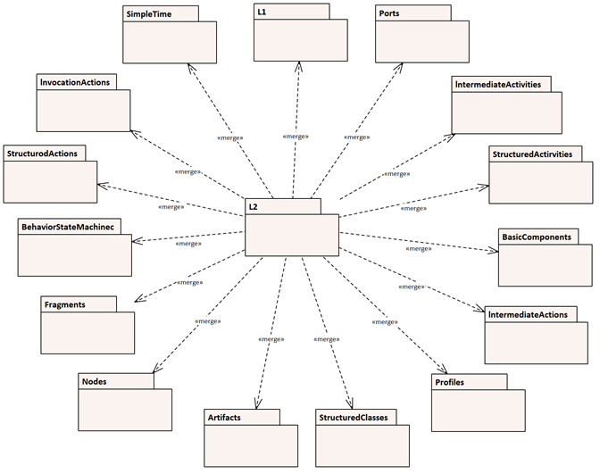
Interpretation of L2
Level 2 adds more language units
and extensions from Level 1. The contents of L2 are
shown in the following diagram:
Figure 2.3-Level
2 top-level package merges
Table 2.4 lists the actual language
units and packages included in this level of compliance.
Table 2.4- Metamodel packages
added in Level 2
| Language Unit
|
Metamodel Packages
|
| Actions |
Actions:StructuredActions |
| Actions::IntermediateActions |
| Activities |
Activities::IntermediateActivities |
| Activities::StructuredActivities |
| Components |
Components::BasicComponents |
| Language Unit
|
Metamodel Packages
|
| Deployments |
Deployments::Artifacts |
|
Deployments::Nodes |
| General Behavior |
CommonBehaviors::SimpleTime |
| Interactions |
Interactions::Fragments |
| Profiles |
AuxilliaryConstructs::Profiles |
| Structures |
CompositeStructures::InvocationActions |
| CompositeStructures::Ports |
| CompositeStructures::StructuredClasses |
| State Machines |
StateMachines::BehaviorStateMachines |
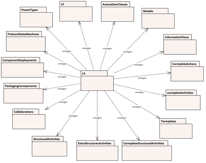
Interpretation of L3
Finally, Level3 contains the full
UML definition, as shown in Figure 2.4.
Figure 2.4- Level
3 top-level package merges
Its contents are shown in Table
2.5
Table 2.5 ®C Metamodel packages
added in Level 3
| Language Unit
|
Metamodel Packages
|
| Action |
Actions::CompleteActions |
| Activities |
Activities::CompleteActivities |
| Activities::CompleteStructuredActivities |
| Activities::ExtraStructuredActivities |
| Classes |
Classes::AssociationClasses |
| Classes::PowerTypes |
| Components |
Components::PackagingComponents |
| Deployments |
Deployments::ComponentDeployments |
| Information Flows |
AuxilliaryConstructs::InformationFlows |
| Models |
AuxilliaryConstructs::Models |
| State Machines |
StateMachines::ProtocolStateMachines |
| Structures |
CompositeStructures::Collaborations |
| CompositeStructures::StructuredActivities |
| Templates |
AuxilliaryConstructs::Templates |
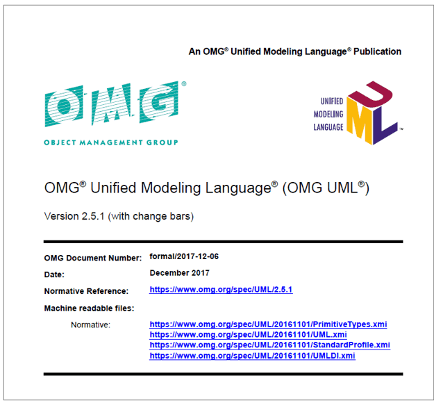
UML 2.5.1 specification
UML 2.5 builds on UML 2.4.1 by
simplifying and reorganizing the UML specification
document. The UML specification has been rewritten
to make it "easier to read" and "as
few forward references as possible". Here's a
screenshot of the specification cover of UML 2.5.1:
There are no longer two separate
UML Infrastructure and UML SuperStructure documents
in the UML 2.5.1 specification, the UML 2.5.1 specification
is a single document. Four UML compliance levels (L0,
L1, L2, and L3) are eliminated because they are not
useful in practice. UML 2.5 tools must support the
full UML specification. Flows, models, and templates
are no longer secondary UML constructs. At the same
time, use cases, deployments, and information flows
become "complementary concepts" in UML 2.5.
A bit of clarification and fixing
has been made to stereotypes, state machines, and
activities. Protocol state machines are now represented
by ?protocol? instead of { protocol }. Use cases no
longer necessarily express the needs of an actor,
which means that a use case is not necessarily initiated
by an actor.
Modeling guidelines for UML
The syntax of UML is concerned
with how UML models are built, represented, and exchanged.
The UML specification defines the syntax of UML from
both abstract and concrete perspectives. However,
the syntax of UML is specified in the framework of
the MOF, and for the purposes of tool consistency,
the meaning of the syntax model is given in the MOF
core specification and the related XMI and graph interchange
specifications.
UML modeling constructs are generally
divided into two semantic categories:
• Structural semantics
define the meaning of UML structural model elements
about individuals in the domain being modeled, which
may only be correct at certain points in time.
• Behavior semantics
define the meaning of UML behavior model elements
that describe how individuals in the domain being
modeled change over time.
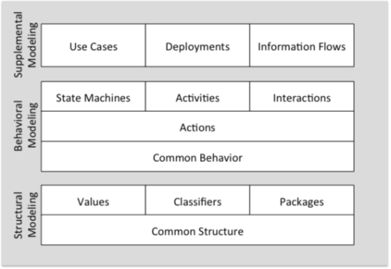
In the UML 2.5.1 specification,
the semantic regions of UML are divided as follows:
Figure
6.1 Semantic Areas of UML
UML semantic regions and the concepts
of these regions are described as follows:
1) Structural Modelling
£∫ The structural semantics of UML provide
the basis for the behavioral semantics of UML. This
reflects the concept of behavioral semantics in terms
of changes in the state of the system specified through
structural modeling. Structural modeling constructs
in UML are built on a common foundation of fundamental
concepts such as types, namespaces, relationships,
and dependencies. Specific modeling constructs include
many different types of classifiers: data types, classes,
signals, interfaces, and components, corresponding
stereotypes for modeling values and instances, and
stereotypes for packaging and profiles.
2) Behavioral Modelling
£∫UML's basic behavior semantics are built
on top of this structure and provide a basic framework
for the execution of behaviors. This common behavioral
semantics also deals with communication between structured
objects that can lead to related behaviors. Note that
this framework only deals with event-driven or discrete
behavior. However, UML semantics do not dictate the
length of time between events. Therefore, the interval
between certain events can be considered the minimum
interval required by the application; For example,
when simulating continuous behavior.
• action is the basic
unit of behavior in UML and is used to define fine-grained
behavior. Their resolution and expressive power are
comparable to executable instructions in traditional
programming languages. Actions can be used with any
advanced form used to describe detailed behavior.
Such high-level behavioral constructs in UML are StateMachine,
activity, and interfaction.
3) Complementary modeling
constructs, which have both structural and
behavioral aspects. These include UseCase, Deployment,
and information flow.
The paradigm defined for model
elements in UML 2.5.1
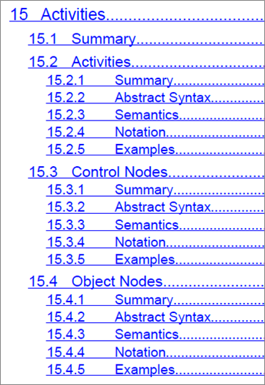
The core content of UML 2.5.1
is to define various UML model elements, so the UML
2.5.1 specification is structured and organized according
to the classification of model elements, and each
UML model element includes the following parts:
• Summary: An overall
introduction
• Abstract Syntax:
A metamodel that describes the composition of elements
• Sematics: A definition
of what an element describes what kind of content
• Notation: A visual
modeling appearance of an element
• Examples: Examples
that reference the modeling of the element
Here's a screenshot of the UML
2.5.1 specification:
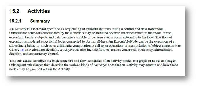
Below is a summary screenshot
of the activities in the UML 2.5.1 specification
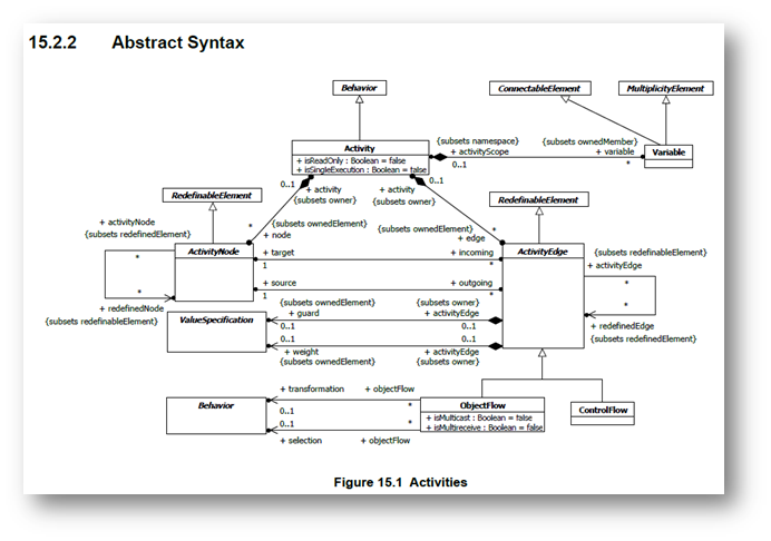
Below is a screenshot of the abstract
syntax definition of activities in the UML 2.5.1 specification
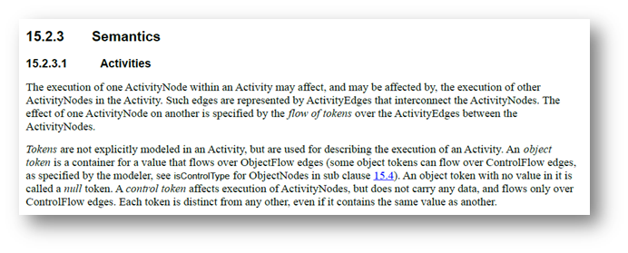
Below is a screenshot of the abstract
semantic definition of activities in the UML 2.5.1
specification
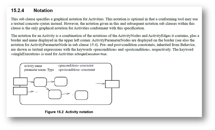
The following is a screenshot
of the markup symbol definition for an activity in
the UML 2.5.1 specification
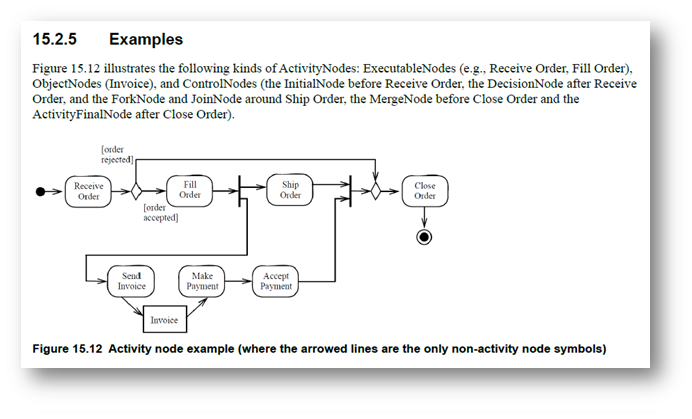
The following is a modeling legend
for an activity in the UML 2.5.1 specification
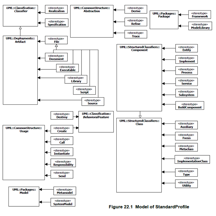
Standard Profile
A Standard Profile specifies a
set of predefined stereotypes. Standards-compliant
tools should support all stereotypes in the Standard
Profile. The following is the Standard Profile model
defined in the UML 2.5.1 specification:
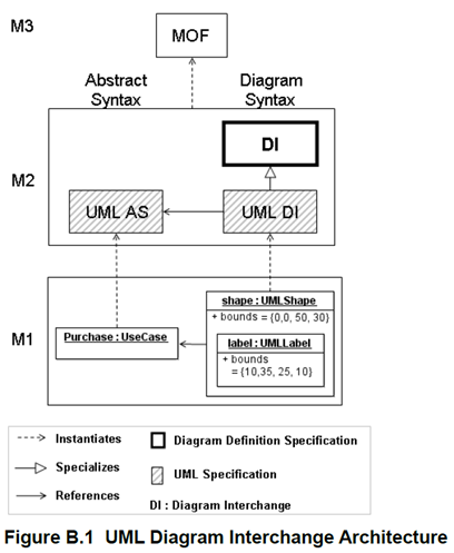
UML Diagram Interchange
In order to properly exchange
UML graphs between various UML modeling tools, the
UML 2.5.1 specification also defines standards for
UML graph exchange. Here's the UML graph exchange
schema:
It can be seen that UML DI is
based on Diagram Definition (DD), which is OMG's specially
defined standard for the exchange of graphs
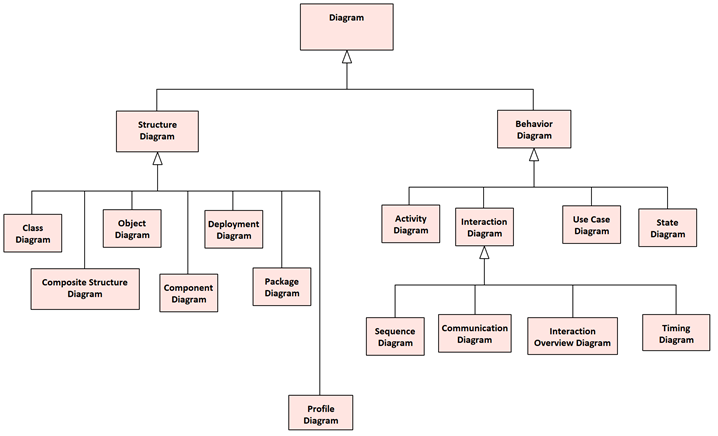
Diagram
There are 14 types of UML diagrams
in the UML 2.5.1 specification, which are divided
into two categories: structure diagram and behavior
diagram.
• The structure diagram
shows the static structure of an object, depicting
those elements that are not time-dependent. The elements
in the structure diagram represent meaningful concepts
in the application and may include abstract, real-world,
and implemented concepts. The structure diagram does
not show the details of the dynamic behaviors (these
are depicted in the behavior diagram). However, it
is possible to show the relationship between the behavior
of the classifier in the structure diagram.
• The behavior diagram
shows the dynamic behavior of objects in the system,
including their methods, collaboration, activities,
and state histories. The dynamic behavior of a system
can be described as a series of changes that occur
in the system over time.
The following are the types of
diagrams defined in the UML 2.5.1 specification:
Figure A.5 The
taxonomy of structure and behavior diagrams
The structure contained in each
UML diagram is described in the following clause.
1. Activity Diagram - Activities
2. Class Diagram - Structured
Classifiers
3. Communication Diagram - Interactions
4. Component Diagram - Structured
Classifiers
5. Composite Structure Diagram
- Structured Classifiers
6. Deployment diagram - Deployments
7. Interaction Overview Diagram
- Interactions
8. Object Diagram - Classification
9. Package Diagram - Packages
10. Profile Diagram - Packages
11. State Machine Diagram - State
Machines
12. Sequence Diagram - Interactions
13. Timing Diagram - Interactions
14. Use Case Diagram - Use Cases
Please note. The classification
of graphs provides a logical organization for the
various major types of graphs. However, it does not
preclude mixing different types of diagram types,
for example, it is possible to model a mix of structural
and behavioral elements together (e.g., to display
a state machine nested within an internal structure).
As a result, the boundaries between the various graph
types are not strictly enforced.
XMI Serialization and Schema
The UML 2 model is serialized
based on the XMI 2 specification, which is performed
according to the rules specified by the MOF 2 XMI
mapping specification.
As a common policy for OMG, the
canonical representation of the MOF 2 and UML 2 models
is an XMI file. The XMI document for UML 2 itself
consists of a single XMI document. The relevant XMI
documentation can be used to specify the StandardProfile
and UML graph exchange models. The PrimitiveTypes
that UML 2 and other specifications rely on are specified
in a separate XMI document.
XMI allows the use of tags to
customize patterns and documents generated using XMI.
Here's an example of a tag setup for some XMI exchanges:
| Swapped elements |
Tag settings for XMI
exchanges |
| UML2 metamodel |
tag "org.omg.xmi.nsPrefix"
is set to "uml" |
| PrimitiveTypes model
library |
tag "org.omg.xmi.nsPrefix"
is set to "primitives" |
| StandardProfile |
tag "org.omg.xmi.nsPrefix"
is set to "StandardProfile" |
| UMLDI metamodel extension |
tag "org.omg.xmi.nsPrefix"
set to "umldi" |
Note: Most of the legends in this
article are from the UML specification, and in order
to improve readability, some of the legends have been
rebuilt using the modeling tools EA and iSpace.
Postscript
I hope you have benefited from
reading this article.
If you are interested in sharing
your experience, please feel free to contribute to
us, and if you are interested in our training, consulting
and tools, please learn about:
• Modeling Tools£∫ EA
• MBSE platform£∫ iSpace
• Course£∫ System Design and Modeling Based on SysML and EA
• Course£∫ System analysis and design based on UML and EA
• Consulting Solution£∫
MBSE (Model-Based Systems Engineering).
• Consulting Solution£∫
Model-driven development based on UML
• All modeling-related
courses£∫ http://www.modeler.org.cn/course/index.asp
• Consulting Solution£∫
Model-Based Project Management
If you
would like to learn more:
Welcome to the Modelers Channel
http://www.mbse-x.com/
Also welcome to contact us
umlooo@hotmail.com
About the Author:
| Zu
Tao ,the founder of Pitaya Software Engineering,
founded Pitaya Software Engineering in 2001 and
IBM Rational User Group in 2004. In 1998, he participated
in the national key research project "Component-based
Software Reuse for Specific Domains" as a
backbone, and was fortunate to learn and use UML
for domain modeling and refine reusable components
and architectures. In the subsequent R&D projects,
the model has been used for analysis and design,
and has accumulated some experience and experience.
In the past experience, the biggest impression
is that the field of software engineering and
systems engineering, which has brought together
many elite talents, has been a messy and confused
state for decades, and from my own experience,
I feel that a clear model is the key to clearing
the fog of engineering, so I continue to study
and apply various modeling techniques, and extract
experience from my own engineering practice, and
form a sustainable methodology for myself, such
as "Nature Model Language- Nature Model Language"
Model-based 3D R&D Management", "iProcess
Process Improvement Method", "Model-based
Requirements Management", "Model-Driven
Architecture Design", "Model-Based Quality
Management", "Model-based Personnel
Capability Management", is currently working
as a product manager and architect, conducting
the research and development of MBSE (Model-Based
Systems Engineering) platform, hoping to establish
model-based engineering solutions, and will continue
to write some articles in the future, hoping to
give some reference to peers.
|
|
 |
|
|