|
Preface
Recently, he undertook the consulting
project "Building a Domain-Specific Modeling
Language with UAF". A detailed interpretation
of the UAF specification is required, and the relevant
UAF specification is read in detail. I found it to
be a very rigorous job to build a modeling language.
All levels of modeling need to be considered in detail
and thoughtfully. Here, a preliminary interpretation
of the UAF specification is given, hoping to provide
some reference for modelers.
References: This article is based
on the UAF1.2 specification.
1. Introduction to UAF
The full name of UAF is Unified
Architecture Framework, which was released by OMG
to unify the architectural modeling of DoDAF, MoDAF,
and NAF. UAF helps commercial companies, federal government
agencies, and defense organizations develop architectural
models. UAF is used for a variety of use cases including
enterprise, mission architecture, system of systems
(SoS), and cyber-physical systems engineering. UAF
is also useful for modeling digital transformation
efforts in enterprises.
UAF evolved from the DoDAF and
MODAF (UPDM) Unified Profile (version 2.1). UAF expands
the scope of UPDM and promotes it to be as applicable
to military architectures as it is to commercial architectures.
The purpose of UAF is to provide a standard formal
approach to describing enterprise architecture using
a model-based systems engineering (MBSE) approach.
The core concepts of UAF are based
on the DoDAF 2.0.2 domain metamodel (DM2) and the
security perspectives of the MODAF Ontology Data Exchange
Mechanism (MODEM), the Canada Department of Defence
Architecture Framework (DNDAF), and the North Atlantic
Treaty Organization (NATO) Architecture Framework
(NAF) v 4.
The UAF model describes a system
from a set of stakeholder concerns, such as security
or information, through a set of predefined perspectives.
The developed model can also reflect a custom viewpoint.
Users can also develop more formal extensions for
new ideas.
UAFML can be used to develop schemas
that comply with the following criteria::
• DoDAF version 2.02
• MODAF version 1.3
• NAF version 3.1
• NAF 4th Edition
Uses of UAF
UAF enables the modeling of strategic
capabilities, operational scenarios, services, resources,
personnel, security, projects, standards, measures,
and requirements; It supports best practices through
the separation of concerns and abstractions. In addition,
UAF supports the modeling of relevant architectural
concepts, such as:
• System-in-a-system
(SoS),
• Information exchange
consistent with the National Information Exchange
Model (NIEM).
• Principles, Organization,
Training Materials, Leadership and Education, Personnel
and Facilities of the Department of Defense (DOTMLPF)
• United Kingdom Ministry
of Defence Development Roadmap (DLOD) elements,
• Human-machine interface
(HCI).°£
In addition, UAF conforms to terms
defined in the ISO/IEC/IEEE 42010 Architecture Description
Standard, such as terms: Architecture, Architecture
Description (AD), Architecture Framework, Architecture
View, Architecture Viewpoint, Concern, Environment.
UAF 1.2 capabilities
The latest version of the UAF
specification is UAF 1.2, UAF v 1.2 supports the following
capabilities:
• Model architectures
for a wide range of complex systems, including hardware,
software, data, people, and facility elements;
• Model a consistent
architecture for the system within the system (SoS)
down to a more specific level of design and implementation;
• Support the analysis,
definition, design and verification of complex systems;
• Improved ability
to exchange schema information between SysML modeling
tools.
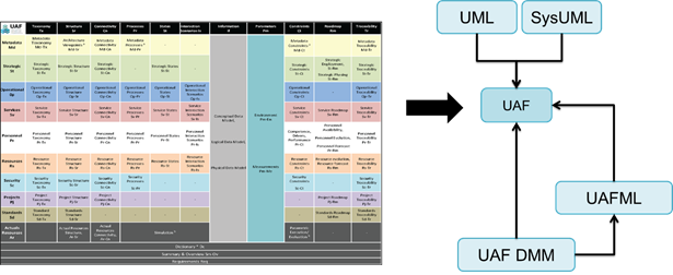
The language architecture of
UAF 1.2
UAF reuses a subset of UML 2.5.1
and SysML 1.6 and provides additional extensions to
meet UPDM 3.0 RFP mandates. These requirements form
the basis of the UAF specification. The UAF specification
explains the design principles of UAF and how to use
UML and SysML to define the UAF language architecture:
• UAF: A unified framework
based on UPDM 3.0 and UML/SysML to unify enterprise
architecture standards for DoDAF, MoDAF, and NAF.
UAF provides an abstraction layer that separates the
underlying UAF metamodel from the presentation layer.
• UAF DMM (DMM): Uses
the UML class model to represent individuals, types,
and tuples that aggregate concepts defined in DoDAF,
MODEM, NAF, DNDAF, and other frameworks.
• UAFML (UA Modeling
Language): is a standard implementation of the UAF
DMM, created by mapping UAF concepts and relationships
to the corresponding stereotypes in UAFML, UAFML analysis
and refactoring reflect language architecture, tool
implementation, and reuse considerations.
Consistency established by UAF
1.2
UAF defines 4 types of conformance
• UAF view specification
consistency. Tools that demonstrate view specification
consistency should implement one version of all view
specifications defined in the UAF grid, with the exception
of view specifications in architecture management
views. Optional tool vendors can implement the framework
perspectives of other donors, such as DoDAF, MODAF
or NAF, based on the mapping between them and the
UAF provided in Appendix A (dtc/21-12-10)
• UAF conceptual syntax
consistency. Tools that demonstrate syntactic consistency
of concepts are consistent with the concepts, relationships,
and constraints defined in the UAF DMM (this document).
UAF conceptual syntax is the foundation for UAF view
specification consistency.
• UAF formal syntactic
consistency. Tools for demonstrating formal syntactic
consistency:
Enable specific UAFML stereotype
instances defined in UAFML:
• Comply with the constraints
defined in UAFML
• Compliant with SysML
version 1.6 specific syntax specifications
UAF formal syntactic consistency
is the basis for UAF conceptual syntactic consistency.
• Consistency of UAF
switching models. A tool that demonstrates model exchange
consistency can import and export consistent XMI for
all valid UAFML models. Model commutative consistency
is the basis for formal syntactic consistency in UAF.
2. UAF 1.2 Specification Interpretation
UAF provides a complete specification
document for enterprise architects, information technology
systems architects, and systems engineers. In addition
to this, investors, managers, software development
engineers, and device development engineers of IT
systems can also get useful references from the UAF
specification.
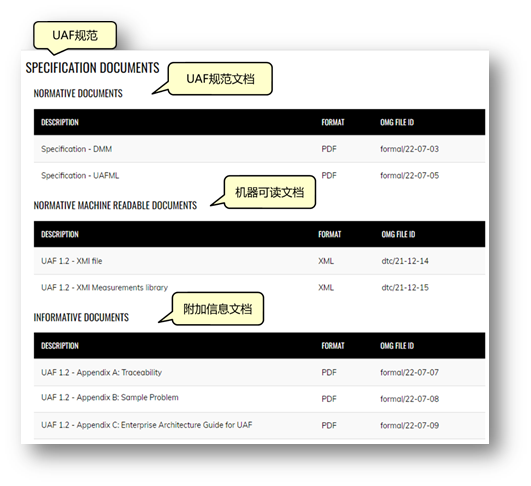
Here is the specification table
for UAF 1.2:
The UAF specification consists
of two formal specification documents:
• DMM (Domain Metamodel):
UAF DMM establishes the underlying foundational modeling
construct for modeling the main entities in the enterprise
and within the enterprise. It provides definitions
of concepts, relationships, and UAF grid view specifications.
The UAF DMM is the foundation for any UAF implementation,
including non-uml/SysML implementations.
• UAFML (UAF Modeling
Language): UAFML provides a modeling language specification
for implementing UAF DMM using UML/SysML
The UAF specification also provides
machine-readable files (in XMI format):
• UAF 1.2 - XMI file
• UAF 1.2 - XMI Measurements
library
These XML files can be imported
into the modeling tool to quickly build relevant model
elements.
The UAF specification also provides
addendum documents:
• Appendix A ®C Traceability:
Provides a mapping between UAF and frameworks (DoDAF,
MODAF, NAF) and languages (SysML, BPMN).
• Appendix B - Sample
Problem: A search and rescue example illustrates the
practical application of UAF.
• Appendix C - Enterprise
Architecture Guide for UAF UAF: Provides a structured
approach to building an EA architecture that uses
UAFML. The EA Guide is intended to be used in conjunction
with the Search and Rescue Mission example in Appendix
B. The approach defined in this guide is just one
of the ways to use UAF to process architectures and
is for informational purposes only and is not an official
OMG authorization method.
2.1 UAF DMM
UAF DMM establishes the underlying
underlying modeling construct for modeling the main
entities in the enterprise and within the enterprise.
It provides definitions of concepts, relationships,
and UAF grid view specifications. UAF DMM is based
on the IDEAS ontology, and everything in this ontology
has four dimensions (time and space), subtypes, and
metrics.
Core Principles
The basic design principles of
UAF DMM are:
• Demand-driven: UAF
is designed to meet UPDM 3.0 RFP mandates.
• Impact of a frame
of reference: A DMM is based on a collection of concepts
and relationships from a frame of reference.
• Driven by IDEAS Ontology:
DMM is a simplified version of the IDEAS ontology
based on it.
• DMM notation: DMM
is modeled using UML class diagrams.
• Reusability of UML
metamodel concepts: The UAF DMM reuses many concepts
from the UML metamodel, such as state machine, activity,
and interaction. Support explicit relationships with
these concepts
• UAF DMM reuses UML
semantics instead of reinventing its own.
• Reusability of BPMN
concepts: UAF DMM reuses many concepts from BPMN,
such as processes.
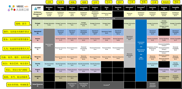
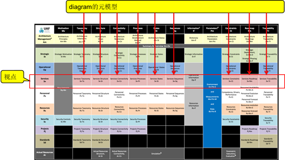
UAF mesh
The model of the DMM is organized
into a number of view specifications, which are organized
in a 2D grid:
• Row: Represents the
viewpoint related to the stakeholder's concern, called
the domain,
• Columns: Describe
the form of the schema, called Aspect.
Cells at the intersection
of rows and columns: A model that describes a viewpoint
of the schema.
UAF Grid Related Notes:
• The view specification
in the Architecture Management perspective helps to
successfully define and develop the architecture artifacts
of the architecture.
• In order to be able
to evaluate architectural behaviors and constraints
(i.e., non-functional requirements), it is necessary
to define instances of architectural elements. Vendors
of tools who want to implement UAF are expected to
provide tools that enable behavioral simulation, measurement
evaluation, and constraints (via parametric diagrams
or specialized equations) or proprietary equivalents
to implement behavioral simulation and evaluation.
• Information models
are a cross-cutting aspect that can take many forms:
conceptual, logical, or physical. Most information
model developers establish a conceptual or logical
form of a data model when using modeling tools.
• In different viewpoints,
parameter columns capture metrics, context, and risk
across the schema.
• The Architecture
Extension View specification provides a way to extend
the framework to other domains.
Here's a brief description
of UAF's point of view:
| Viewpoint |
Abbreviation |
Description |
| Architecture Management |
Am |
Identify the metamodels
and views needed to develop an architecture that
serves the purpose. |
| Strategic |
St |
Competency management
process. Describe the classification, combination,
origin, and evolution of capabilities. |
| Operational ( ≤Ÿ◊˜ ) |
Op |
Describe the logical
architecture of the enterprise. Describe the requirements,
operational behaviors, structure, and exchange
requirements for support capabilities. Define
all operational elements in a form that is implementation/solution
agnostic |
| Service |
Sv |
• A service-oriented
view (SOV) is a description of a service that
directly supports operations in an operations
view. In MODAF, a service is understood in the
broadest sense - a unit of work through which
the provider provides a useful result to the consumer.
• DoDAF: The service view in the service
viewpoint describes the design of a service-oriented
solution to support the Operations Development
Process (JCIDS) and the Defense Acquisition System,
or capability development in the capability domain. |
| Personel |
Ps |
Define and explore
organizational resource types. Displays the type
taxonomy of your organization's resources, as
well as links, interactions, and past growth. |
| Resources
|
Rs |
Nothing more than a
solution architecture that includes the resources,
organization, software, artifacts, capabilities,
and natural resources to meet operational requirements.
The further design of a resource can be refined
using SysML and UML. |
| Security
|
Sc |
Security assets and
safety exclusion zones. Define the hierarchy of
security assets and asset owners, security constraints
(policies, laws, and guidance), and the details
of where they are located (security exclusion
zones). |
| Project
|
Pj |
Describe projects and
project milestones, how those projects deliver
functionality, the organizations that contribute
to the project, and the dependencies between projects. |
| Standard |
Sd |
MODAF: The technical
standards view extends from the core DoDAF view
to include non-technical standards such as operating
principles, industry process standards, and more.
DoDAF: A standard view in a standard viewpoint
is a set of rules that govern the arrangement,
interaction, and interdependencies of parts or
elements of a solution. |
| Actual Resources
|
Ar |
Analysis, for example,
evaluation of different alternatives, assumptions,
trade-offs, V&V on actual resource allocation.
Describe the actual resource allocation that is
expected or realized |
Here's a brief description of
the UAF aspect:
| Aspect |
Abbreviation |
Description |
| Motivation |
Mv |
Capture the motivational
elements associated with the organization's transformation
efforts, such as challenges, opportunities, and
concerns, as well as different types of requirements,
such as operations, services, people, resources,
or security controls. |
| Taxonomy (taxonomy) |
Tx
|
Render all elements
as separate structures. Represent all elements
as a specialized hierarchy, providing a text definition
for each element and referencing the element's
source |
| Structure |
Sr |
Describe the decomposition
of structural elements, such as logical performers,
systems, projects, etc., into smaller parts |
| Connectivity |
Cn |
Describe the connections,
relationships, and interactions between different
elements. |
Process
|
Pr |
Capture activity-based
behaviors and flows. It describes the activities,
their inputs/outputs, activity operations, and
the flow between them. |
| State |
|
Captures the state-based
behavior of an element. It is a graphical representation
of the state of a structural element and how it
responds to various events and actions. |
| Sequence |
Sq
|
Represents a chronological
examination of the exchange that occurs due to
a specific scenario. Based on the results of a
particular scenario, the exchange between the
participating elements is checked chronologically. |
Information
|
If |
Handle an informational
perspective of operations, services, and resource
architecture. Allows you to analyze the information
and data definition aspects of the architecture
without having to consider the specific problems
of the implementation |
| Constraint |
Ct |
Describe in detail
the measure of performance requirements that are
set up to constrain capacity. Rules that govern
behavior and structure are also defined. |
Roadmap
|
Rm
|
Explain how elements in the schema change over
time. |
Traceability
|
Tr |
Describe the mapping
between elements in the schema. This can be between
different viewpoints within a domain, or between
different domains. Mappings can also be between
structure and behavior. |
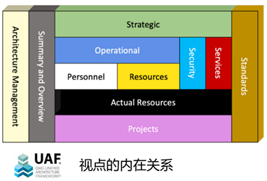
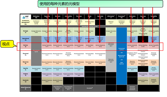
The interrelationship of perspectives
Although UAF Grid is the primary
means of expressing the relationships between viewpoints,
aspects, and view specifications, due to its two-dimensional
nature, it is insufficient to explain the abstract
interrelationships that exist between viewpoints.
The chart below shows how these perspectives relate
to each other.
• Horizontal viewpoints
indicate that viewpoints exist in an abstraction layer,
with interrelationships between viewpoints above and
below it and between viewpoints to the left and right.
• The vertical viewpoint
depicts cross-cutting concerns across levels of abstraction
in the architecture.
Domain metamodel legend
Pay attention to the colors in
the diagram to help the reader understand the model.
Please refer to the legend below to understand the
diagram.
Here are the elements of the element
colors used in the DMM and what they represent.
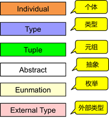
The meaning of element types in
UAF is based on the concepts proposed in IDEAS (International
Defense Enterprise Architecture Specification).
• Individual represents
a single instance of an element
• Type indicates a
group of individuals
• Tuple denotes the
relationship that exists between the elements
• Abstract indicates
that an element has no direct purpose, but is only
a means of construction
• Enumation is a complete,
ordered list of all items in a collection
• External Type is
an element that exists outside of the core DMM, but
can be referenced by elements in the DMM
Metamodel in DMM
The DMM provides 2 meta-models:
• Domain MetaModel Diagram:
A metamodel of the diagram used to describe the various
viewpoints of the UAF.
• Domain MetaModel
Element: The modeling element used in each viewpoint
of the UAF is defined using a metamodel.
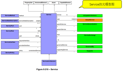
Domain MetaModel Diagram
A metamodel of a diagram that
describes the various viewpoints of UAF. That is,
the diagram for each form of description for each
viewpoint of the UAF is defined using a metamodel.
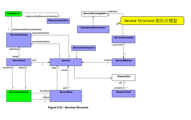
Here's a diagram of the MetaModel from the service
viewpoint:
The following is the metamodel
definition of the structure diagram of the service,
including: a text description, a metamodel diagram,
and a list of elements:
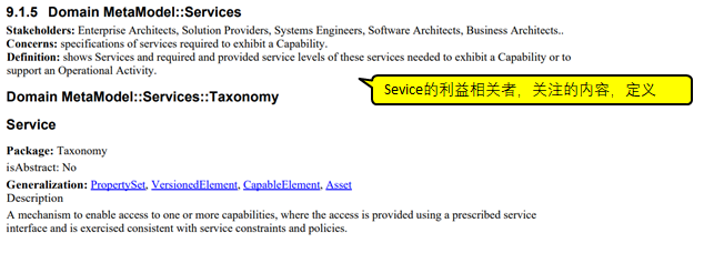
View
Specifications::Services::Structure
Contains the diagrams that
document the Services Structure View Specification.
View Specifications::Services::Structure::Services
Structure
• Stakeholders:
Solution Providers, Systems Engineers, Software
Architects, Business Architects.
• Concerns: combination
of services required to exhibit a capability.
• Definition:
shows the composition of services and how services
are combined into a higher-level service required
to exhibit a capability or support an operational
activity.
• Recommended
Implementation: SysML Block Definition Diagram,
SysML Internal Block Diagram.
Elements
• Implements
• Measurement
• OperationalInformation
• PropertySet
• ResourceInterface
• Service
• ServiceArchitecture
• ServiceConnector
• ServiceExchangeItem
• ServiceInterface
• ServiceMethod
• ServiceParameter
• ServicePort
• ServiceRole |
Domain MetaModel Elements
That is, the modeling element
used in each viewpoint of the UAF is defined using
a metamodel. The same element may be used in multiple
diagrams. The following is illustrated with a metamodel
of the element from the Service viewpoint.
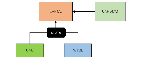
2.2 UAFML
UAFML defines the language in
which the content of UAF is modeled, and UAFML specifies
a UAF Profile file that enables modelers to express
architectural model elements and organize them in
a set of perspectives, aspects, and view specifications
to support the specific needs of end users in defense
and commercial, industrial.
UAFML defines a set of stereotypes,
model elements, and relationships to meet the requirements
of the UPDM 3.0 RFP and UAF DMM. The UAFML specification
specifies the language architecture based on the UML
profiling mechanism. Many UAFML stereotypes inherit
from SysML stereotypes, where SysML semantics need
to be reused. The reusable parts of the SysML specification
are not directly included in the specification, but
are used through prototype inheritance. The UAFML
specification reuses a subset of UML 2.5.1 and SysML
1.7 and provides additional extensions needed to address
UPDM 3.0 RFP mandates.
The core principles of UAFML
• Demand-driven: The
UAFML goal is to meet the UPDM 3.0 RFP mandate.
• UAF Domain Metamodel
(DMM) drive: DMM serves as the basis for profiling
development.
• Reuse existing specifications:
UAFML reuses UML/SysML in any real-world scenario
to meet the needs of UAFP 3.0 RFPs and leverages the
features of UML and SysML to provide robust modeling
capabilities. Therefore, UAFML is essential for supporting
UML 2. x and SysML 1.x vendors are relatively easy
to implement.
• Compliance level:
UAFML has a single compliance level, which is based
on a combination of UML and SysML element reuse. The
expectation is that the view created by this profiling
file has a framework that reflects the type of underlying
SysML diagram that is used as the basis for the view.
One would also expect graphical representations to
be used to display elements in those views, which
corresponds to the standard SysML graphical representations
for the SysML/UML metaclasses of stereotype-extended.
• Interoperability:
UAFML inherits XMI interchange capabilities from UML.
The UAFML specification reuses a subset of UML 2.5.1
and provides additional extensions needed to address
UPDM 3.0 RFP mandates.
Describe the Stereotype constraint
The UAF modeling language uses
enhanced standard notation to graphically represent
metaconstraints in UAFML diagrams to improve the readability
of the UAFML specification and overcome the limitations
of not being able to visualize constraints graphically
in UML.
Meta constraints appear in UAFML
canonicals for visualization purposes only, but are
represented in XMI as UML constraints, specified in
structured English. These constraints are achievable
in tools, such as through OCL.
A simple UML profile takes these
metaconstraints.
The definition of a meta-constraint
profile in the UAFML profile is described in detail
below.
Metaconstraint dependency
• °∂metaconconstraint°∑
is a stereotype that extends the Dependency metaclass.
It is used to specify the constrained elements in
the profile.
• An example of a °∂metaconconstraint°∑
dependency dependon is a graph of a stereotyped extension.
• MapsToCapability
is a UAFML stereotype that extends Abstraction, a
type of Dependency in UML. The constraint of this
stereotype is that its client must be stereotyped
by the activity (which is abstract), and its supplier
must be constructed by the capability. However, because
it is not possible to display this constraint graphically,
the diagram does not convey the desired information.
Therefore, we use the "metaconconstraint"
dependency to visualize the constraints.
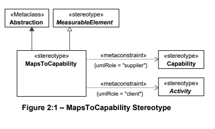 As meta-constraint dependencies
are added to the graph (see Figure 2:1), this suggests
that MapsToCapability is a prototype of an extended
abstract metaclass that inherits the properties of
a MeasurableElement and is used to model the relationship
between an activity (or its subclasses) and capability
(or its subclasses). A MapsToCapability constructed
by a Dependency construct must have a value that is
constructed as a client property of an activity, and
the value of its supplier property must be constructed
as a Capability.
Note - When the stereotype extends
the Connector, the values of the stereotype properties
umlRole are "end[0]"" and "end[1].role.
°±
This is done because the Connector
does not have a direct "link" to the element
being connected; It links to Connector Endings, which
references the element being linked. Thus, end[n]
provides a reference to ConnectorEnd, while role provides
a reference to the linked element.
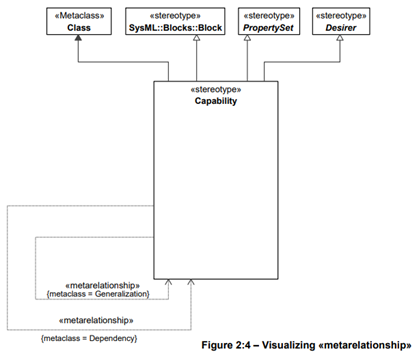
Metarelationship dependency
°∂metarelationship°∑ is a dependency
stereotype that shows that certain domain concepts
will be implemented using regular UML relationships.
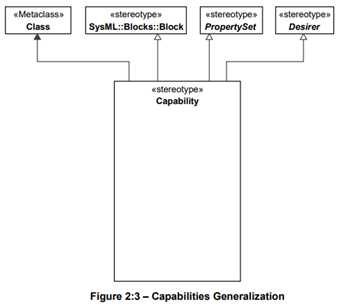
For example, a Capability may
depend on other Capabilities, or a subtype of a Capability,
but this concept cannot be shown on a diagram:
We use ?metarelationship? dependency
to visualize the concepts of dependency and generalization.
This diagram should be read as
follows:
Capability
can be related to other capabilities, in this
case using UML Dependency metaclass, ;
Capatility can also have subtypes of other Capability,
in which case UML's Generalization metaclass is
used. |
°∂metarelationship°∑dependency will
only be displayed on the graph of the specification,
but not in profile XMI.
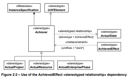
Stereotyped relationship dependency
Although °∂metarelationship°∑ dependency
creates a good way to show the constrained side of
a construct relationship, it also incurs some overhead
when displaying a relationship with two stereotypes.
For example, Figure 2:2 shows that there is a constructive
relationship between an element of type Achiever and
an element of type ActualState called "AchievedEffect".
UAF Stereotype
The UAF Stereotype chapter of
the UAFML specification provides metamodels of the
various stereotypes in UAFML.
UAFML profile imports the entire
SysML profile. This is designed for seamless integration
with system modeling using SysML so that the capabilities
that SysML brings can be fully leveraged. An example
of this is the integration of requirements into UAFML,
as well as the use of parametric diagrams and element
integration based on instance specifications, so that
UAFML can be used for metric evaluation during architecture
development.
Here's a screenshot of the element
stereotypes from the UAFML specification document:
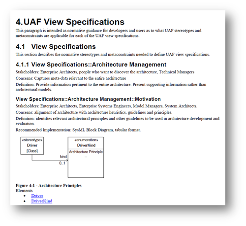
UAF View Specification
The sections of the UAF View Specification
provide a metamodel of the various views of UAF. The
intent is to provide specification guidance to developers
and users on which UAF stereotypes and meta constraints
apply to each UAF view specification.
Here's a screenshot of a view
metamodel in the UAF View Specification:
Postscript
I hope you have benefited from
reading this article.
If you are interested in sharing
your experience, please feel free to contribute to
us, and if you are interested in our training, consulting
and tools, please learn about:
• Modeling Tools£∫ EA
• MBSE platform£∫ iSpace
• Model web browsing
tool£∫ WebEA
• Course£∫ System
Design and Modeling Based on SysML and EA
• Course£∫System
analysis and design based on UML and EA
• Consulting Solution£∫
MBSE
(Model-Based Systems Engineering).
• Consulting Solution£∫
Model-driven
development based on UML
• All modeling-related
courses£∫ http://www.modeler.org.cn/course/index.asp
• Consulting Solution£∫
Model-Based
Project Management
If you
would like to learn more:
- Welcome to the Modelers Channelhttp://modeler.org.cn/
- Also welcome to contact us
directly at zhgx@uml.net.cn £¨010-62670969
About the Author:
| Zu
Tao, the founder of Dragon Fruit Software Engineering,
founded Dragon Fruit Software Engineering in 2001
and IBM Rational User Group in 2004. In 1998,
he participated in the national key research project
"Component-based Software Reuse for Specific
Domains" as a backbone, and was fortunate
to learn and use UML for domain modeling and refine
reusable components and architectures. In the
subsequent R&D projects, the model has been
used for analysis and design, and has accumulated
some experience and experience. In the past experience,
the biggest impression is that the field of software
engineering and systems engineering, which has
brought together many elite talents, has been
a messy and confused state for decades, and from
my own experience, I feel that a clear model is
the key to clearing the fog of engineering, so
I continue to study and apply various modeling
techniques, and extract experience from my own
engineering practice, and form a sustainable methodology
for myself, such as "Nature Model Language-
Nature Model Language" Model-based 3D R&D
Management", "iProcess Process Improvement
Method", "Model-based Requirements Management",
"Model-Driven Architecture Design",
"Model-Based Quality Management", "Model-based
Personnel Capability Management", is currently
working as a product manager and architect, conducting
the research and development of MBSE (Model-Based
Systems Engineering) platform, hoping to establish
model-based engineering solutions, and will continue
to write some articles in the future, hoping to
give some reference to peers.
|
|
 |
|
|