|
1. Introduction to FACE
FACE is an abbreviation for Future
Airborne Capability Environment.
The purpose of FACE is to establish
an integrated framework for avionics airborne systems
so that suppliers of different subsystems can be easily
interconnected, improving the opportunity for resource
reuse, with the ultimate goal of reducing the development
cost, integration cost and delivery time of avionics
capabilities.
FACE has been adopted by the United
States Office of Naval Aviation Air Warfare Electronics
Program (PMA-209), Army Program Executive Office (PEO)
Aviation (AVN), Army Center for Aviation and Missile
Research, Development and Engineering (AMRDEC), and
Air Force Research Laboratory (AFRL).
This article will provide an overview
of the content of the FACE architecture, including
the following:
• Segmentation of FACE's
logical architecture
• Standardized interface
for FACE
• FACE's data architecture
• An example of a reference
architecture segment for FACE
• Compiler language
runtime
• Component frameworks
• Profiles of operating
system segments
• UoC and UoP (Consistency
Units and Portable Units)
2.Segmentation of the FACE architecture
The FACE reference architecture
consists of logical segments that have changed. The
structure created by these segments connected together
is the basis of the FACE reference architecture.
The five segments of the FACE
reference architecture are as follows:
1. Operating System Segment (OSS)
2. Input/Output Services Segment
(IOSS)
3. Platform-Specific Services
Segment (PSSS)
4. Transport Services Segment
(TSS)
5. Portable Components Segment
(PCS)
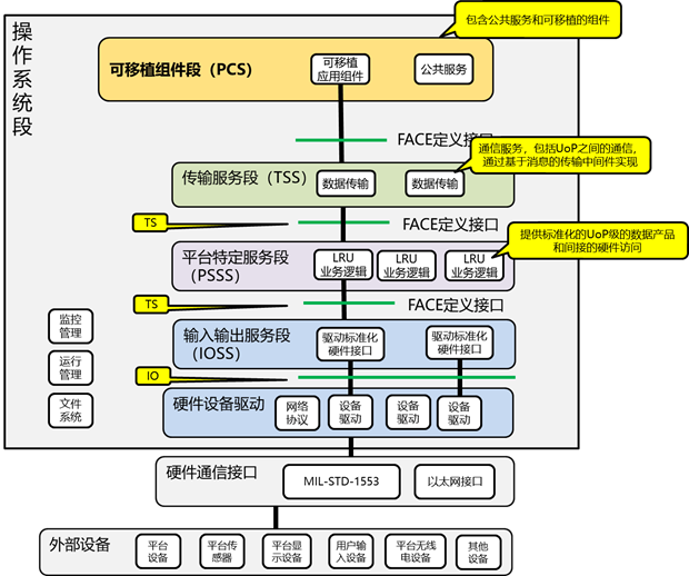
The following are the functions
of each architecture segment
| Operating System Segment
(OSS) |
It provides system
services, which can adapt to various operating
systems, and provides common basic services, such
as operation scheduling, network services, device
services, component management, and configuration
services. |
| Input/Output Services
Segment (IOSS) |
Provides an abstraction
of hardware drivers and focuses on interface data
rather than hardware and software drivers. |
| Platform-Specific Services
Segment (PSSS) |
Provide platform-related
services, including:
? Platform-Specific Device Services (PSDS): Supports
the conversion between data management and platform-specific
interface control documents (ICDs) and FACE UoP
delivery models (USMs).
? Platform-specific public services (PSCS): Includes
log services, Device Protocol Mediation (DPM)
services, streaming media, health monitoring and
fault management (HMFM), and configuration services.
? Platform-Specific Graphics Services (PSGS):
Abstract the interface details of graphics processing
units (GPUs) and other graphics devices from software
components in the FACE reference architecture. |
| Transport Services
Segment (TSS) |
To provide communication
services. Abstract transport mechanisms and data
access from software components to integrate into
different architectures and platforms using different
transport methods. Data distribution between TSS
PCS and/or PSSS UoCs. TSS features include, but
are not limited to, distribution and routing,
prioritization, addressability, association, abstraction,
transformation, and component state persistence
of software component interface information. |
| Portable Components
Segment (PCS) |
Consists of software
components that provide functionality and business
logic. PCS components are portable and interoperable,
so they are hardware agnostic and cannot be tied
to any data transfer or operating system implementation. |
3.Standardized interface for
FACE
The FACE reference architecture
defines a standardized set of interfaces that provide
connectivity between segments of the FACE architecture.
The standardized interfaces in the FACE reference
architecture are the Operating System Segment Interface
(OSS Interface), the I/O Service Interface (IOS Interface),
the Transport Service Interface, and the Component-Oriented
Support Interface. Software references to these standardized
interfaces can be established at initialization, startup,
runtime, etc.
| Interface type |
illustrate
|
| Operating system segment
interface |
The OSS interface provides
a standardized way for software to use services
and other OSS-related features within the operating
system. OSS interfaces are provided by OSS UoC
to UoCs on other network segments. The interface
includes arinc653, POSIX?, and HMFM APIs. OSS
interfaces can optionally include one or more
of the following networking functions: programming
language runtime, component framework, lifecycle
management, and configuration service interfaces.
|
| Input/output service
interfaces
| The IOS interface provides a standardized way for
software components to communicate with device
drivers. The interface supports several common
I/O bus architectures. |
| Transport service interfaces
| The Transport Services Interface provides a standardized
way for software to use the communication services
provided by TSS. A specific type (TS) interface
is provided by a software component within the
TSS and is used for communication with the software
components within PSSS and PCS. The FACE data
architecture manages the representation of data
traversing the transport service interface. |
| Component-oriented
support interfaces
| Component-oriented support interfaces include injectable
interfaces and lifecycle management service interfaces,
which are FACE standardized interfaces for cross-cutting
concerns of component support. |
| Injectable interface |
Injectable interfaces
provide a standardized way for integrated software
to address the inherent usage/provision interface
dependencies between software components. In order
for a software component to use an interface,
it must be integrated in the same address space
as at least one software component that provides
the interface. The injectable interface implements
the dependency injection idiom of software development. |
| Lifecycle Management
Service Interface |
The Lifecycle Management
(LCM) service interface provides a standardized
way for software components to support behavior
consistent with the component framework: initialization,
configuration, framework start/teardown, and operational
state transitions. The LCM service interface can
be optionally provided by software components
in any FACE reference architecture segment and
can be selectively used by a system integration
implementation or software components in any FACE
reference architecture segment. |
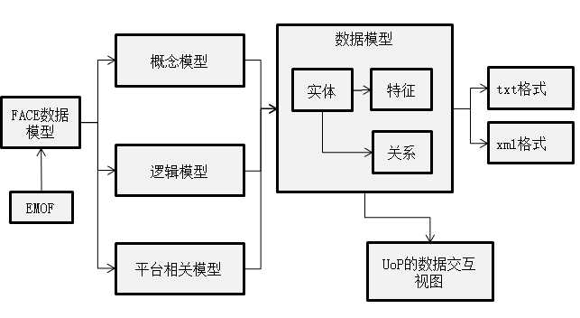
1.1 FACE Data Architecture
The FACE data schema is clearly
defined in the FACE specification, and the definition
of the FACE data schema includes the following parts
:
• The FACE Data Model
Language leverages Open UDDL (Open Universal Domain
Description Language) to define the SDM (Shared Data
Model) for FACE and the USM (UoP (Portability Unit)
for the provided model
• Define the FACE data
model language, specified by the EMOF (Basic Meta-Object
Facility) metamodel and a set of OCL (Object Constraint
Language) constraints
• Define a template
language to specify the representation of data elements
across key FACE interfaces
• Define the FACE Data
Model Language Binding Specification, describing how
the elements specified in the Open UDDL technical
standard are mapped to data types and/or structures
for each supported programming language
• Provides SDM to allow
the use of standardized definitions across all FACE
conformance data models
• Define the build
rules for USM
Each PCS UoC, PSSS UoC, or TSS
UoC that uses the TS interface comes with a USM that
is consistent with the FACE SDM and defines its interface
according to the FACE Data Model Language. A domain-specific
Data Model (DSDM) captures content related to the
domain of interest and can be used as the basis for
a USM. The DSDM must be consistent with the FACE SDM.
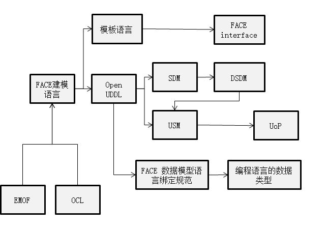
FACE Data Model Language
The FACE data model language forces
a multi-level approach to modeling entities and their
associations at the conceptual, logical, and platform
levels, supporting progressive and varying degrees
of abstraction. Entities, their characteristics, and
associations provide context for defining the view
specification for data exchange between UoPs.
The FACE Data Model Language supports
the modeling of abstract UoPs, provides a canonical
mechanism for sourcing or defining elements based
on FACE technical standards, and can be used in other
reference architectures. To address the integration
problem between UoPs, the FACE data model language
provides elements that describe the high-level connections,
routing, and transformations to be embodied in the
transport service instance.
The FACE technical standard contains
different representations of the FACE data model language::
• Lists of text generated
from metamodels ;
• Extensible Markup
Language (XML) Metadata Exchange (XML) manifests exported
from the metamodel, which need to conform to the appropriate
EMOF.
Data architecture governance
The FACE SDM Governance Plan specifies
the authority and operating parameters of the FACE
SDM Configuration Control Board (CCB). The FACE SDM
governance program manages growth through expansion
and ensures the necessary alignment of new SDM elements.
SDM consists of basic elements and any extensions
in the Conceptual Data Model (CDM), Logical Data Model
(LDM), and Platform Data Model (PDM). The FACE SDM
Governance Program details a complete process, set
of rules, and roles and responsibilities for FACE
SDM CCBs, vendors, and system integrators.
1.2 Example of a reference architecture
segment for FACE
Here's an example of an application
based on the FACE architecture:
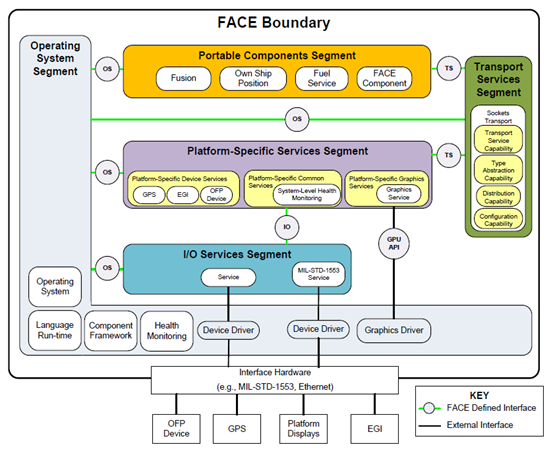
Examples:
There is a simple system that
receives navigation data from a Global Positioning
System (GPS) device and provides its own ship position
symbol to the display via MIL-STD-1553 interface hardware.
The software is implemented as several components
designed for reuse and portability.
The following describes the relationships
between the various FACE sections within the example
system:
| location |
Function |
| Peripherals |
Under the FACE Boundary,
GPS devices collect sensor data and pass navigation
data in a device-specific format to a MIL-STD-1553
compliant bus. Device drivers are written to specific
MIL-STD-1553 hardware, and the data format is
specific to the GPS device. |
| OSS |
Within the "FACE
Boundary", OSS provides a set of public APIs
and FACE operating system services. This allows
software that conforms to FACE's operating system
interface specification to run on top of many
different FACE OS implementations. |
| IOSS |
Data from device drivers
can be accessed using common operating system
APIs, and at the time of access, unique implementations
can be converted into a standardized format by
services in IOSS to abstract the uniqueness of
MIL-STD-1553 devices. This abstraction allows
software that uses the same external devices to
be deployed on systems that use different I/O
devices.
|
| PSSS |
The I/O service passes
this data to PSSS through a standardized interface
defined by the FACE technology standard, in this
case the GPS platform device service. This device
service provides an abstraction of a specific
GPS communication, typically described in the
ICD of that device, and converts this data into
a standard structure and semantics according to
the FACE data architecture.
|
| TSS |
This data is transferred
by the Transport Service Capability and Distribution
Capability to the software component that needs
the data to be processed, in this case, the Own
Ship Position PCS component, depending on the
configuration. In this example, the transport
service leverages the transport mechanisms provided
by OSS, specifically POSIX sockets. All data to
and from the PCS is routed through the TSS.
|
| PCS |
This Own Ship Position
component computes the graphical symbol and sends
it back through the transport service using a
well-defined graphical language. In this case,
TSS is configured to distribute these graphics
messages to a platform-specific graphics service
in PSSS. The platform-specific graphics service
then draws to the display through the graphics
driver.
|
This scenario highlights how to
use the FACE reference architecture to isolate changes
to the system. For example:
• If a GPS device is
replaced with a different GPS, the relevant platform
device service will be replaced or modified.
• If the MIL-STD-1553
bus is changed, then the I/O service will be replaced
or modified.
• If the transfer mechanism
is changed, the transfer service will be replaced
or modified.
In all of these cases, the portable
component is isolated from these changes.
1.3 Programming Language Run-Times
In order to achieve the goals
of the FACE reference architecture, the programming
language runtime also needs to be considered. The
FACE technical standard imposes limitations on programming
languages. The use of standardized programming languages
is fundamental to building portability. The FACE programming
language runtime mechanism selects more common programming
languages such as C, C++, Ada, and Java as alternative
programming languages. The programming language runtime
can be provided as part of OSS or included in a software
component that resides in another section.
The interface between the operating
system and software components can be replaced or
enhanced with a programming language runtime. The
POSIX API set is typically provided in the form of
a programming language runtime.
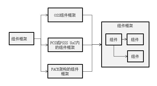
1.4 Component Frameworks
The FACE technical standard supports
the use of component frameworks. Component frameworks
provide supporting functionality for software components.
There are three ways to use the component framework
in the FACE reference architecture:
• Component framework
provided by OSS (Operating System Segment)
The component framework is provided as part of OSS.
The component framework provided by OSS extends the
OSS interface to include the component framework's
own APIs. The component framework provided by OSS
is limited to the component framework specified in
the OSS interface requirements.
• Component framework
inside the PCS or PSSS UoC
The complete component framework is an integral part
of the PCS or PSSS UoC and follows the permissible
PCS and PSSS interfaces. This approach takes advantage
of the convenience of component framework development
and allows for FACE alignment, but can have an impact
on performance, integration, and/or resources.
• Component framework
that implements the FACE reference architecture The
component framework used
across multiple FACE segments implements the Framework
Support Capability (FSC). FSC is an abstraction that
converts a component framework interface into a FACE-oriented
interface.
OSS and TSS support common frameworks,
allowing software to be developed in compliance with
both component frameworks and FACE technology standards.
1.5 Operating System Segment
Profile
The FACE reference architecture
defines three FACE OSS Profiles to tailor operating
system (OS) APIs, programming languages, programming
language features, runtimes, frameworks, and graphics
capabilities to meet the needs of critical software
components at different levels. The three FACE OSS
Profiles are:
• Security
• Safety
• Base
• Extended
• General
Purpose |
The limitations of the OS API
and each profile are illustrated in the following
diagram:
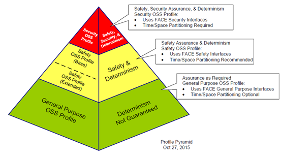
Figure 3: FACE
OSS Profile Diagram
Here's a description of each FACE
OSS profile:
| FACE OSS Profile |
illustrate |
| Security profile |
Limiting operating
system APIs to the smallest useful set allows
evaluation of high-assurance security features
performed in a single address space (for example,
a POSIX process or an ARINC 653 partition). Security
Profile requires ARINC 653 support. |
| Safety Profile |
The Safety Profile
is less restrictive than the Security Profile
and restricts the operating system APIs to those
with a security certificate family tree. The Safety
Profile consists of two sub-profiles:
• The Safety Base Sub-profile supports
a single POSIX process application with a broader
set of operating system APIs than the Security
Profile.
• Safety Extended Sub-profile includes
all Safety Base Sub-profile OS APIs, as well as
additional OS APIs and optional support for multiple
POSIX processes.
Safety Profile requires ARINC 653 support. |
| General Purpose Profile
|
The General Purpose
Profile is the least constrained profile that
supports operating system APIs that meet real-time
deterministic or non-real-time non-deterministic
needs, depending on the implementation of the
system or subsystem. ARINC 653 support and multiple
POSIX processes are optional |
Tip: Although the naming of Security
and Safety Profiles reflects their primary design
focus, their use is not limited to services with these
needs (i.e., software components that do not have
safety or security design concerns can be restricted
to using only one of these profiles' operating system
APIs).°£
1.6 UoC and UoP (Consistency
Unit and Portability Unit)
A unit of conformance (UoC) is
a software component or domain-specific data model
designed to meet the applicable requirements defined
in the FACE technical standard. It is referenced as
a UoC at any stage of its development and becomes
a UoC for FACE certification upon completion of the
FACE conformance process. The FACE technical standard
contains separate requirements for each FACE segment
and for the UoC in each FACE OSS Porfile.
A Portability Unit (UoP) is a
UoC that resides in a PCS or PSSS.
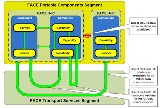
Fig. Communication
between and within UoCs in PCS
UoC packages can be used to contain
features that are made up of multiple UoCs. UoC packages
that comply with FACE technical standards can be developed
in accordance with FACE's UoC specifications.
Postscript
I hope you have benefited
from reading this.
If you are willing to share
your experience, please submit it to us.
If you are interested in
our training, consulting and tools:
Course£ļ
Tool£ļ
Consulting
Options£ļ
If you would like to learn more:
About the Author:
Zu Tao, the founder of Dragon Fruit Software Engineering,
founded Dragon Fruit Software Engineering in 2001
and IBM Rational User Group in 2004. In 1998,
he participated in the national key research project
"Component-based Software Reuse for Specific
Domains" as a backbone, and was fortunate
to learn and use UML for domain modeling and refine
reusable components and architectures. In the
subsequent R&D projects, the model has been
used for analysis and design, and has accumulated
some experience and experience. In the past experience,
the biggest impression is that the field of software
engineering and systems engineering, which has
brought together many elite talents, has been
a messy and confused state for decades, and from
my own experience, I feel that a clear model is
the key to clearing the fog of engineering, so
I continue to study and apply various modeling
techniques, and extract experience from my own
engineering practice, and form a sustainable methodology
for myself, such as "Nature Model Language-
Nature Model Language" Model-based 3D R&D
Management", "iProcess Process Improvement
Method", "Model-based Requirements Management",
"Model-Driven Architecture Design",
"Model-Based Quality Management", "Model-based
Personnel Capability Management", is currently
working as a product manager and architect, conducting
the research and development of MBSE (Model-Based
Systems Engineering) platform, hoping to establish
model-based engineering solutions, and will continue
to write some articles in the future, hoping to
give some reference to peers.
|
|
 |
|
|