|
1°¢What is UAF
UAF stands for Unified Architecture
Framework, published by OMG, with the aim of unifying
the architecture modeling of DoDAF (United States
Department of Defense Architecture Framework), MoDAF
(United Kingdom Department of Defense Architecture
Framework), and NAF (NATO Architecture Framework).
UAF helps commercial companies, federal government
agencies, and defense organizations develop architectural
models. UAF is used for a variety of use cases such
as enterprise mission architecture, systems of systems
(SoS), and cyber-physical systems engineering. UAF
is also useful for modeling digital transformation
efforts in enterprises.
The UAF model describes a system
from a set of stakeholder concerns, such as security
or information, through a set of predefined perspectives.
The developed model can also reflect a custom viewpoint.
Users can also develop more formal extensions for
new ideas.°£
2 °¢ UAF use
The UAF architecture model provides
a way to understand complex systems and the relationships
that exist between organizations, systems, and systems,
and to be able to analyze these systems to ensure
that they meet user expectations.
UAF can create models such as:
Strategic Capabilities, Operational Scenarios, Services,
Resources, People, Security, Projects, Standards,
Measures, and Requirements; It supports best practices
through the separation of concerns and abstractions.
In addition, UAF supports the modeling of related
architectural concepts, such as::
• System (SoS)
• Information exchange
in accordance with the National Information Exchange
Model (NIEM).
• Department of Defense
Doctrine, Organization, Training, Equipment, Leadership
and Education, Personnel and Facilities (DOTMLPF)
• United Kingdom Ministry
of Defence Roadmap (DLOD) elements
• Human Machine Interface
(HCl)
In addition, UAF complies with
terms defined in the ISO/IEC/IEEE 42010 architecture
description standard, such as terms: architecture,
architecture description (AD), architecture framework,
architecture view, architecture perspective, concerns,
environment, model type, stakeholders.
3 °¢ What does UAF have?
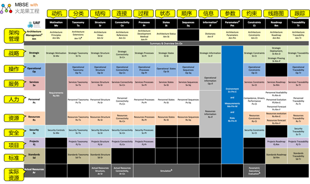
The latest UAF specification is
the UAF v1.2 specification, and the UAF framework
borrows from the Zachman framework representation
in the description, as shown in the following figure:
A grid is a way to show how the
various perspectives (referred to as view specifications
in the rest of the document) correspond to the domains
(horizontal rows) and model types (columns) that describe
the view specifications. The purpose of the mesh is
not to be complete, but to capture the information
present in the framework that would help the UAF,
so some gaps are obvious.
Figure UAF grid
Concentrate:
Row: Represents the viewpoint
related to the stakeholder's concern, called the domain
Columns: Describe the form of
the schema, called an aspect
Cells at the intersection of rows
and columns: A model that describes a viewpoint of
the schema.
A brief description of the definition
of a viewpoint
| Viewpoint |
Acronym |
Description |
| Schema management |
Am |
Identify the metadata and views
needed to develop a suitable architecture for
its purpose. |
| stratagem |
St |
Competency management process.
Describe capability classification, composition,
dependency, and evolution. |
| operate |
Op |
Explain the logical architecture
of the enterprise. Describe the requirements,
operational behaviors, structures, and interchanges
required to support (demonstrate) capabilities.
Define all operational elements in a way that
is implementation/solution independent. |
| serve
|
Sv
| A service-oriented view (SOV) is
a description of the services required to directly
support a run-domain, as described in Run-View.
Service in MODAF: is understood in the broadest
sense as a unit of work through which the provider
delivers useful results to the consumer. Services
in DoDAF: The Services view in the Services viewpoint
describes the design of a service-based solution
to support the Operational Development Process
(JCIDS) and defense acquisition systems or capability
development within the Joint Capability Area.
|
| manpower
|
Ps |
Define and explore organizational
resource types. Displays a categorization of your
organization's resource types and connectivity,
interactions, and growth over time. |
| resource |
Rs |
Captures the solution architecture
that consists of resources, such as organization,
software, artifacts, capability configurations,
and natural resources to fulfill operational needs.
The further design of the resource is usually
detailed in SysML or UML. |
| safe |
Sc |
Safe assets and safe areas. Define
the hierarchy of security assets and asset owners,
security constraints (policies, laws, and guidelines),
and the details in which they are located (security
enclaves). |
| project |
Pj |
Describe projects and project milestones,
how those projects deliver functionality, the
organizations that contribute to the project,
and the dependencies between projects. |
| standard |
Sd |
MODAF: The technical standards
view is an extension of the core DoDAF view to
include non-technical standards such as operational
doctrines, industry process standards, and more.
DoDAF: A standard view in a standard viewpoint
is a set of rules that govern the arrangement,
interaction, and interdependencies of parts or
elements of a solution. |
| Actual resources |
Ar
| Analysis of actual resource allocation,
e.g. evaluation of different alternatives, what-if
analysis, trade-offs, V&V. Describe the actual
resource configuration that is expected or realized. |
A brief description of the definition
of the aspect
| aspect
| Acronym
| Description
|
| motivation
|
Mv |
Capture motivators,
such as challenges, opportunities, and concerns,
related to enterprise transformation efforts and
different types of needs, such as operations,
services, people, resources, or security controls.
|
| classify
|
Tx |
Renders all elements
as independent structures. Render all elements
as a specialized hierarchy, providing a text definition
for each element and referencing the element's
source |
| structure
|
Sr |
Descriptions break
down structural elements (e.g., logical performers,
systems, projects, and so on) into smaller parts
|
| connect
|
Cn |
Describe the connections,
relationships, and interactions between different
elements. |
| process
|
Pr |
Capture activity-based
behaviors and processes. It describes the activities,
their inputs/outputs, activity actions, and the
flow between them. |
| state
|
St |
Captures the state-based
behavior of an element. It is a graphical representation
of the state of a structural element and how it
responds to various events and actions. |
| sequence
|
Sq |
Represents a time-ordered
interchange check as a result of a specific scenario.
As a result of a particular scenario, the exchange
between the participating elements is examined
chronologically. |
| Information
|
If |
Address an information
perspective on operations, services, and resource
architecture. Allows the information and data
definition aspects of the architecture to be analyzed
without having to think about implementation-specific
issues. |
| restraint |
Ct |
Detail the measure
of the ability to set up performance requirements
constraints. Rules that govern behavior and structure
are also defined. |
| road map
| Rm
| Address how elements
in the architecture change over time. |
| trace
| Tr
| Describe the mapping
between elements in the schema. This can be between
different perspectives within and between domains.
It can also be somewhere between structure and
behavior. |
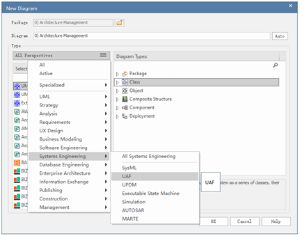
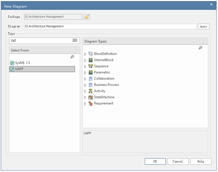
4 °¢ What is EA's support for
UAF
In EA, you can create UAF models
Here are a few model diagrams
of UAF
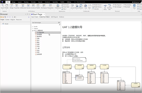
We also provide a model framework
for UAF that allows you to quickly create UAF models.
Includes UAF modeling guides, model templates, and
model samples.
5.Create a UAF model with civilian
maritime search and rescue (SAR).
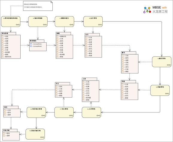
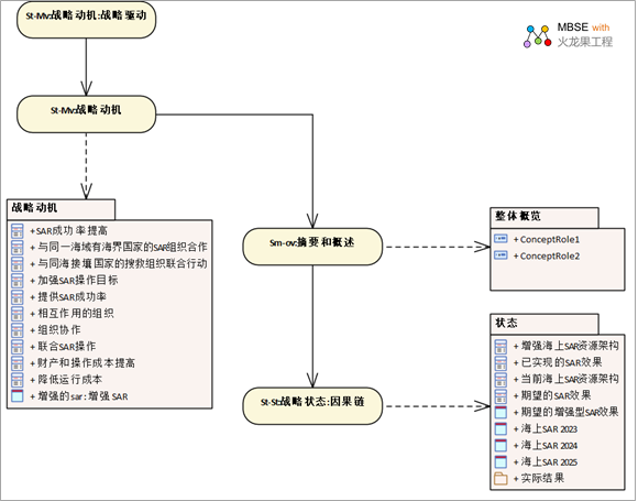
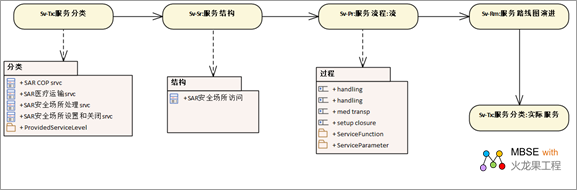
Taking the UAF model as an example
of civil maritime search and rescue, the following
figure shows the package structure of the model. It
reflects the main areas of UAF:
Let's take a look at each of them
5 °¢1 Architecture management
Stakeholders: Enterprise architects,
architect-focused people, technical managers.
Focus: Capture metadata related
to the entire schema.
Definition: Provides information
related to the overall architecture. Provide supporting
information, not an architecture model
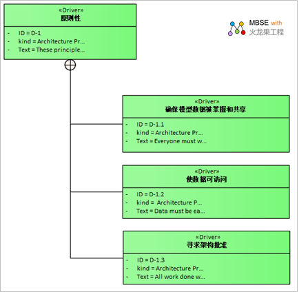
Architecture Management::Motivation
Identify relevant architecture
principles and other guidelines to be used in architecture
development and evaluation
The following diagram shows the
principles used in the development of the SAR architecture.
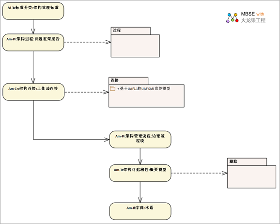
Architecture Management::Traceability
It displays references to operations,
services, and resource architectures, asset libraries,
legacy architectures, and external sources such as
documentation.
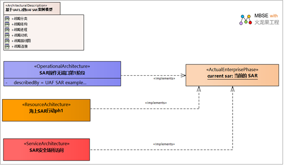
The following diagram depicts
the traceability between the schema description and
the operational, service, and resource schema:
5 °¢ 2 Summary and Overview (SM-OV)
Stakeholders: decision makers,
solution providers, systems engineers, software architects,
business architects.
Focus: A quick overview and analysis
summary of the architecture description. It is a planning
guide developed in the initial stages of the architecture.
Once the schema is complete, it provides a summary
of the findings, as well as any analysis that has
been conducted.
Definition: Provides executive-level
summary information in a consistent form for quick
reference and comparisons between architectures. The
summary and overview includes assumptions, constraints,
and constraints that may influence the high-level
decision-making process involving architecture
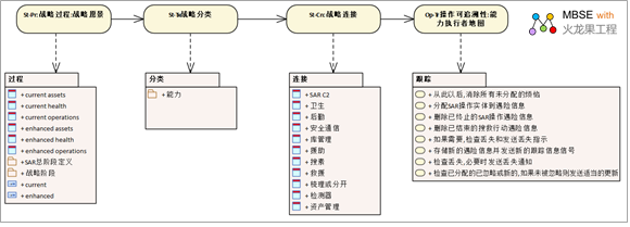
5 °¢ 3Strategic Perspective (ST)
Stakeholders: Competency portfolio
managers.
Focus: Competency management process.
Definition: Describes the classification,
composition, dependencies, and evolution of capabilities
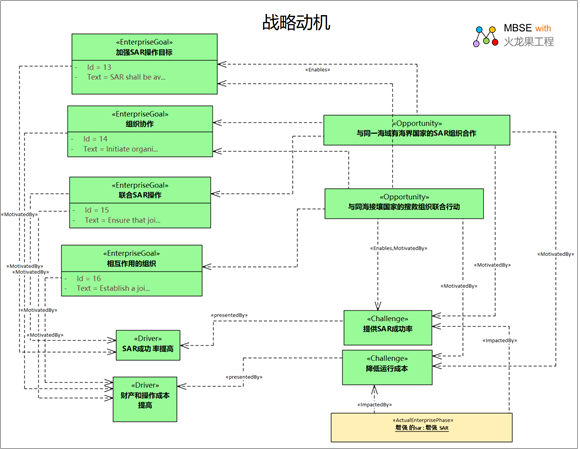
The following diagram illustrates
the challenges, opportunities, and concerns associated
with business transformation efforts:
Strategic Motivation
Identify and define the drivers,
challenges, and opportunities that apply to the architecture.
Defines the desired outcomes, goals and objectives
driven by drivers, and opportunities to achieve them.
The following shows the challenges,
opportunities, and concerns associated with business
transformation efforts:
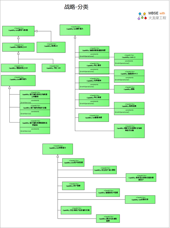
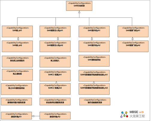
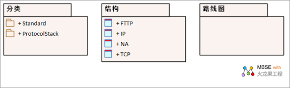
Strategic::Taxonomy
Features need to be described
in terms of the attributes they need to exhibit that
enable the business to use them to achieve enterprise
goals, and how they relate within the inheritance
hierarchy.
The following is a classification
of features in a SAR model that is shown
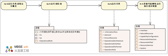
5 °¢4 Running viewpoint (Op)
Stakeholders: Business architects,
executives
Focus: Explain the logical architecture
of the enterprise.
Definition: Describes the requirements,
operational behaviors, structures, and exchanges required
to support (demonstrate) capabilities. Define all
operational elements in a way that is independent
of the implementation/solution.
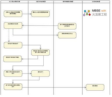
Operational::Processes
It describes the activities that
are typically undertaken in the process of achieving
the operational objectives of supporting capacity.
It describes operational activities, their inputs/outputs,
operational activity actions, and the flow between
them.
The following diagram shows the
flow of the distress signal active and invalid handling
activities:
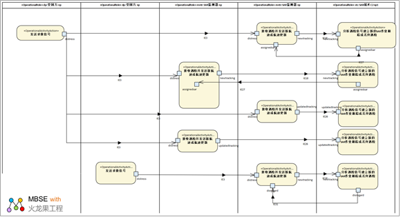
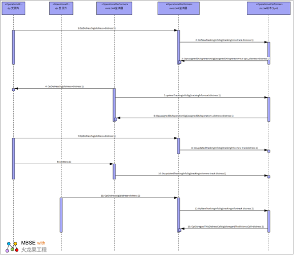
Operational::Sequences
It provides a chronological check
of the exchange of operations between participating
nodes (action performer roles) as a result of a particular
action scenario.
OP-IS is used to define time-based
behavioral scenarios between operational elements.
Interactions can be service actions as well as interactions
defined on the OP-SR and OP-PR diagrams.
The following is an interactive
scenario for the operation of valid and ineffective
distress signal handling:
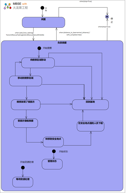
Operational::States
It is a graphical representation
of the state of the performer of an action action
and how that action performer responds to various
events and actions.
The following diagram shows the
operational state of the rescue state machine:
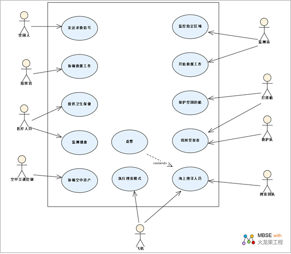
Operational::Use Cases
It describes the use cases that
are typically performed in the process of achieving
business goals that support the enterprise.
A mission defines a functional
goal that stakeholders have. This is consistent with
the definition of a use case. Because UAF is built
on top of SysML, it is possible to create a use case
diagram that shows the tasks, their relationships,
and the stakeholders involved in the tasks. The following
diagram defines the tasks required for search and
rescue.
5 °¢ 5 Service Perspective ( SV
)
Stakeholders: Enterprise Architects,
Solution Providers, Systems Engineers, Software Architects,
Business Architects.
Focus: Service specifications
required to demonstrate competency.
Definitions: Displays the requirements
and levels of service provided by service specifications
and those specifications required to demonstrate capabilities
or support combat activities.
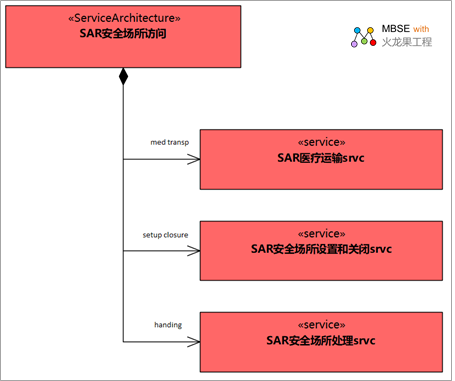
Services::Structure
It shows the composition of services
and how they can be combined into high-level services
that are required to display functionality or support
operational activities.
The following diagram defines
a service architecture with three services that handle
security location processing. The purpose of this
service architecture is to completely outsource the
handling of the safe place, i.e., the service architecture
deals with the setup and closure of the safe place,
any medical transportation required, and the actual
operation of the safe place in operation.
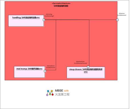
Services::Connectivity
It specifies the service interface,
for example, the service method, signal reception,
and/or stream properties that are provided and required
to ensure the compatibility and reusability of the
service.
The actual internal structure
of the SAR Secure Premises Access Service Architecture
is shown in the following diagram. Notably, it displays
an interface around, which means that settings and
shutdowns as well as medical transport are invoked
by the SAR Safe Premises Processing Service.
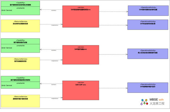
Services::Traceability
It describes the mapping of services
to operational activities and how services contribute
to the implementation of functionality.
The following diagram shows which
services contribute to the functionality and which
services support operational activities
Service traceability from function
to service to operational activity
5 °¢6 Personnel Viewpoint ( PS
)
Stakeholders: HR, solution providers,
project managers.
Concern: Human factors.
Definition: Aims to elucidate
the role of human factors (HF) in the creation of
architectures to facilitate human factors integration
(HFI) and systems engineering (SE).
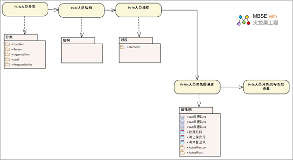
Personnel::Taxonomy
It shows a breakdown of your organization's
resource types.
The following diagram shows the
classification of personnel in search and rescue organizations.
Personnel::Roadmap:Availability
It defines the requirements and
functions to ensure that the right number of actual
people with the right competencies and the right number
of people are competent for the actual position.
The following diagram defines
the actual people and the dates they fill the actual
positions, which also defines the availability of
people.
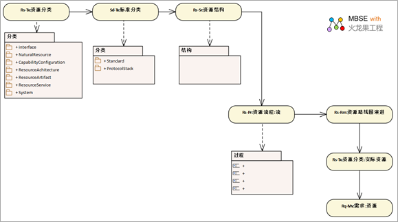
5 °¢ 7 Resource Viewpoint (RS)
Stakeholders: Systems Engineers,
Resource Owners, Implementers, Solution Providers,
IT Architects.
Focus: Define the solution architecture
to meet operational requirements.
Definition: Captures the solution
architecture that consists of resources, such as the
organization, software, artifacts, capability configurations,
and natural resources that implement operational requirements.
The further design of the resource is usually detailed
in SysML or UML.
Resources::Taxonomy
Displays a categorization of resource
types.
RS-TX defines the different types
of resources that will be used to implement the logical
schema defined in the operations view. Elements include
resource services, resource artifacts, systems, and
services.
The following diagram shows the
SAR resources that are primarily related to Phase
1.
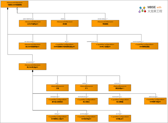
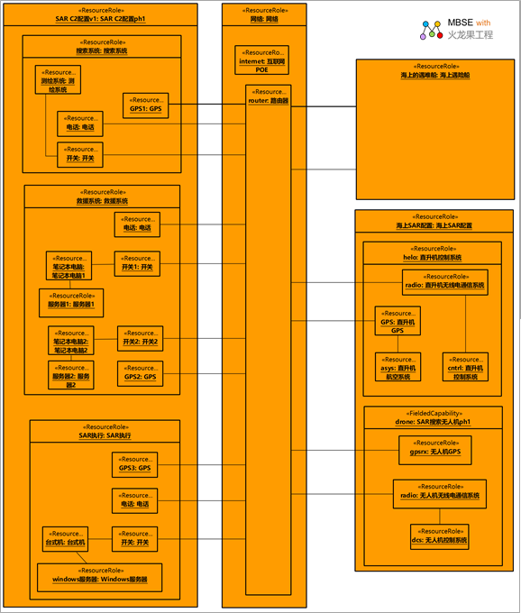
Resources::Structure
Physical resources, such as the
capability configurations/systems and interactions
required to implement a particular set of operational
performers, are defined. Can be used to represent
the communication network and path that connects the
communication resource and provides details about
its configuration.
The resource structure of Phase
1 is shown in the following diagram. It is divided
into two different layers in order to handle the actual
service of a given operation in the second layer.
This makes it easy to process multiple SAR operations
in parallel. It should be noted that due to the fact
that specific natural resources are included as boundary
conditions for SAR processing. There are also references
to some elements other than formal parts of the architecture.
The reason for this is that they can't really be architecturally
modified, and they're important things outside of
the SAR resource architecture. The elements defined
in this way are public health services, the Internet,
and cellular networks.
Resources::Processes
Describes the functions that are
typically performed in the course of implementing
business activities that support competency. It describes
the functions, their inputs/outputs, functional operations,
and the flow between them.
RS-PR defines the functions performed
by different types of resources. The following diagram
shows a small example of a resource flow flow detailing
the actions taken to get the drone to take off.
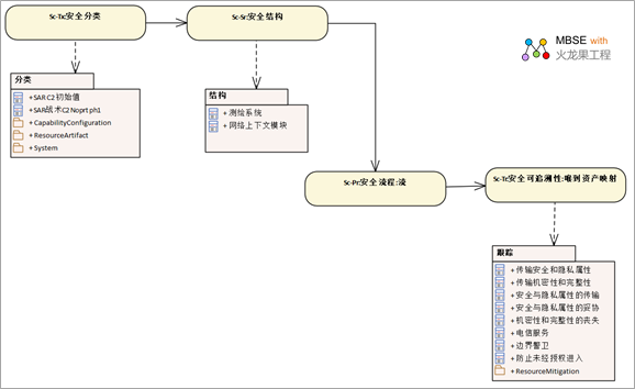
5 °¢ 8 Safety Viewpoint (SC)
Stakeholders: Security Architects,
Security Engineers, Systems Engineers, Operations
Architects.
Concern: Address the security
constraints and information assurance attributes that
exist in the exchange between resources and action
performers
Definition: Describe the security
assets, security constraints, security controls, series,
and measures required to address a specific security
issue.
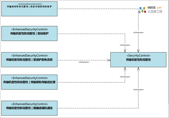
Security::Motivation
Identify security controls to
mitigate security risks.
The following diagram is a safety
motivation view that shows the applicable enhancements
to Safety Control (SC) 8.
Security::Connectivity
List secure exchanges between
secure assets; applicable security controls; and the
safe enclave where exchange producers and consumers
are located. Measurements can be included selectively.
The module definition diagram
is associated with the network context block element
and is used to generate the network diagram (see Parameter
view). As shown in the following network analysis
resource network diagram, it is easy to reference.
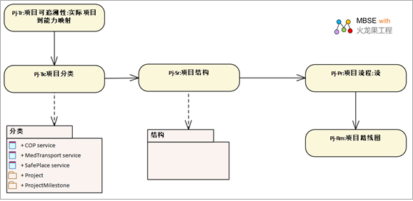
5 °¢9 Project Viewpoint ( Pj )
Stakeholders: Project Managers,
Portfolio Managers, Enterprise Architects.
Focus: Portfolios, projects, and
project milestones.
Definition: Describes projects
and project milestones, how these projects deliver
capabilities, and how the organization contributes
to projects and dependencies between projects.
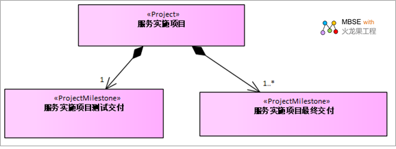
Projects::Structure
Provide a template for the actual
project roadmap to be implemented.
The PJ-SR block type diagram provides
a way to define projects and project types. In the
following diagram, the service implementation project
consists of two milestones, final delivery and test
delivery
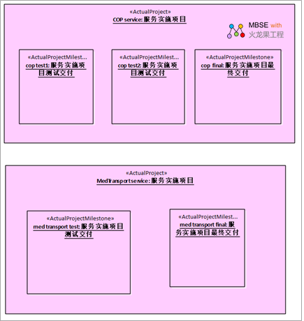
Projects::Connectivity
Shows how projects and project
milestones are related sequentially.
PJ-CN provides a way to define
actual projects, actual project milestones, and the
relationships between them. The diagram below gives
the two SAR projects and their project milestones.
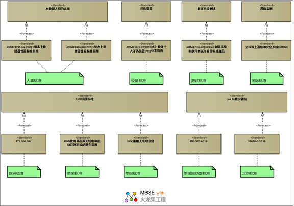
5 °¢ 10 Standard viewpoint (SD)
Stakeholders: Solution Providers,
Systems Engineers, Software Engineers, System Architects,
Business Architects.
Focus: Technical and non-technical
standards that apply to the architecture.
Definitions: Displays the technical,
operational, and business standards that apply to
the architecture. Define the basic criteria for current
and anticipated conditions.
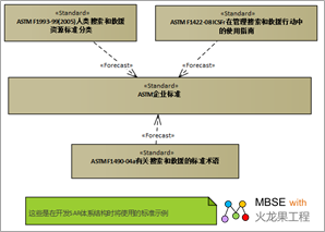
Standards::Roadmap
Define the basic criteria for
current and anticipated conditions. Expected criteria
are those that can reasonably be predicted in light
of the current state of the technology and expected
improvements/trends.
UAF provides block diagrams and report formats for
SD-TX. The block diagram form provides a way to define
criteria and their attributes, as well as to associate
standard predictions with them.°£
The diagram below shows the SAR
standards offered by ASTM. ASTM International, originally
known as the United States Society for Testing and
Materials (ASTM), is now an international standards
body whose standards range from recreational aviation
safety, to fiber optic cable installation in underground
utilities, to homeland security. More information
can be found on www.ASTM.org. The spans shown are
for illustrative purposes only. They often denote
emerging standards.
The diagram below shows the various
standards for marine radio, Link 16 and distress monitoring.
These are part of the capability configuration shown
in the RS-SR diagram.
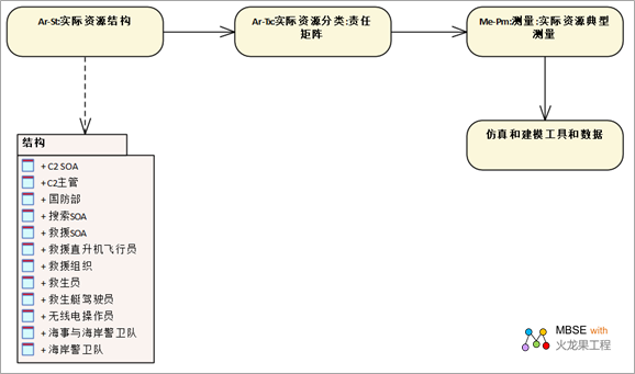
5 °¢11 Actual Resource Viewpoint
(AR)
Stakeholders: Solution Providers,
Systems Engineers, Business Architects.
Concern: Analysis of actual resource
allocation, such as evaluation, assumptions, trade-offs,
validation & validation of different alternatives.
Definition: Describes the actual
resource configurations that are expected or realized
and the actual relationships between them.
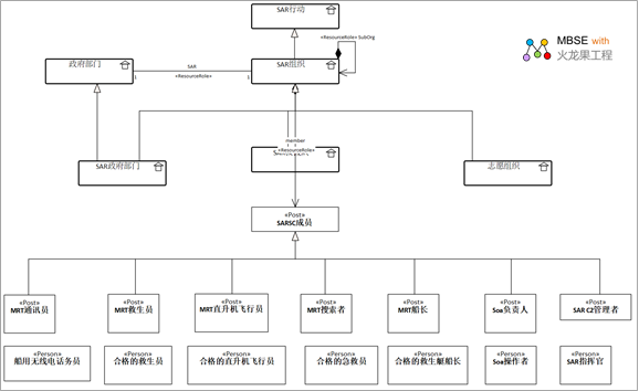
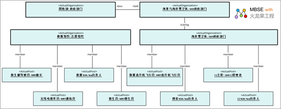
Actual Resources::Structure
Describe the actual resource configuration
that is expected or realized to meet operational needs.
The diagram below shows the internal
personnel structure of an actual search and rescue
organization.
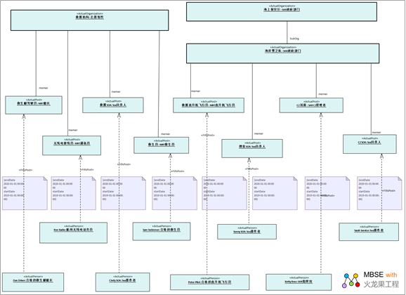
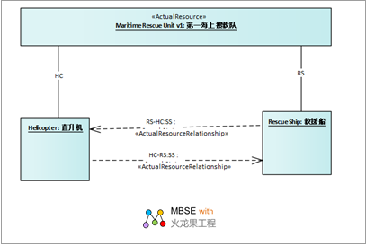
Actual Resources::Connectivity
Explain the actual resource allocations
and the actual relationships between them.
The following diagram shows a
nominal architecture to illustrate an example of system
interaction.
The above is the introduction
of the UAF model sample. We have also prepared a special
course for you: "UAF Architecture System and
Practice"!
This course will take you through
real-world examples of how to analyze the design,
how to model, how to model the various viewpoints
of UAF's architecture, how to verify the model-based
simulation, and realize the full cycle of model-based
tracking.
postscript
I hope you have benefited
from reading this.
If you are willing to share
your experience, please submit it to us.
If you are interested in
our training, consulting and tools:
Course:
Tool£∫
Consulting
Options:
If you would like to learn more:
|