|
The class diagram is the main modeling form of code structure, and in order to make the reader see it more vividly, the mapping relationship between the class diagram and the code is introduced in the form of a legend.
Here's a legend for a design class diagram:
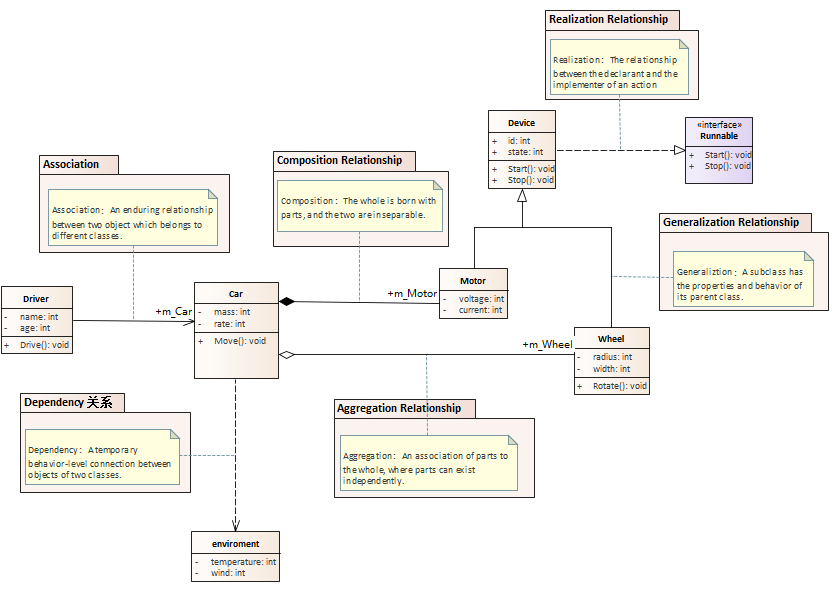
The following is a class diagram and a code example (C++ code) of the relationships between classes:
1) Association
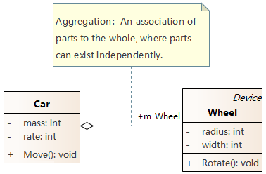
2) Aggregation
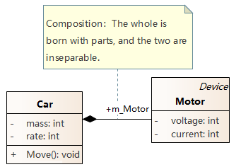
3) Composition
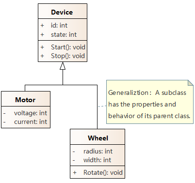
4) Generalization
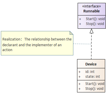
5) Realization
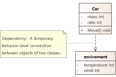
6) Dependency
Relationship of Classes:
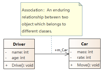
Association
The Driver can drive the Car, and the relationship between the two has been around for a long time.
 |
#include "Car.h"
class Driver
{
public:
Driver();
virtual ~Driver();
Car *m_Car; //assocation╣žŽĄ
void Drive();
private:
int name;
int age;
}; |
Aggregation
Car aggregates wheels, and wheels can exist independently of cars.
 |
class Car : public Device
{
public :
Car ();
virtual ~ Car ();
Wheel * m_Wheel ; //aggregation ╣žŽĄ
Motor m_Motor ;
void Move ();
private :
int mass ;
int rate ;
};
|
Composition
Car contains Motor, which is an integral part of Car.
 |
#include "Wheel.h"
class Car : public Device
{
public :
Car ();
virtual ~ Car ();
Wheel * m_Wheel ;
Motor m_Motor ; //composition ╣žŽĄ
void Move ();
private :
int mass ;
int rate ;
}; |
Generalization
Motor and Wheel are subclasses of Device, inheriting the properties of Device: id and state, methods: Start() and Stop()
 |
#include "Device.h"
class Wheel : public Device
{
public :
Wheel ();
virtual ~ Wheel ();
void Rotate ();
private :
int radius ;
int width ;
}; |
Realization
Device implements the Start() and Stop() methods of the Runnable interface.
|
#include "Runnable.h"
class Device : public Runnable //Realization ╣žŽĄ
{
public :
Device ();
virtual ~ Device ();
int id ;
int state ;
void Start ();
void Stop ();
}; |
Dependency
The car's move operation relies on enviroment
 |
#include "Wheel.h"
#include "environment.h"
class Car
{
public :
Car ();
virtual ~ Car ();
Wheel * m_Wheel ;
Motor * m_Motor ;
void Move ( enviroment e ); //dependency ╣žŽĄ
private :
int mass ;
int rate ;
}; |
Note: The model in this article uses the modeling tool EA to model and generate code.
UML Diagram Series:
Postscript
I hope you have benefited from reading this.
If you are willing to share your experience, please submit it to us.
If you are interested in our training, consulting and tools:
|